
Terminal Operations
Fuel terminal automation in Indonesia: how it works and how to prepare an implementation
How a fuel terminal automation system runs a TBBM day to day, which components sit in each layer, which Indonesian rules shape the design, and what to prepare before an implementation starts.
- Topic
- Terminal Operations
- Updated
- 18 November 2026
- Reading time
- 8 min
- Sections
- 8
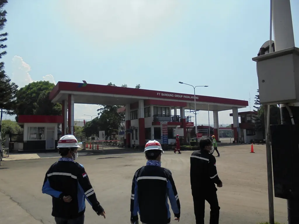
A fuel terminal automation system is the combination of field instruments, controllers and software that runs receipt, storage and truck loading at a fuel terminal (TBBM), and records every quantity directly from the measuring devices. In Indonesia it usually means a terminal automation system (TAS) for the loading side and a tank management system (TMS) for the tank side, connected to SAP. For the basic definition, see what a TAS is; for the terminal itself, see what a TBBM is.
This guide is written for people who will run, buy or support such a system at an Indonesian terminal. It follows one loading cycle from start to finish, maps the components layer by layer, lists the regulations that shape the design, and ends with the preparation work that most often decides whether an implementation goes smoothly. The examples come from Citia's projects at Pertamina terminals.
How it works
How one loading cycle runs
A fuel terminal automation system works by checking each step of a truck's visit against the step before it, so that no truck loads without a valid order and no litre leaves without a record. The cycle starts in SAP, where the sales order or shipment becomes a loading order that the TAS can read. At the gate, the driver taps an RFID or NFC card; the TAS checks that the truck, its driver and the order belong together, and the gate opens only if they do.
The truck then waits in a queue until the TAS assigns a bay. At the bay the driver connects the earth clamp and the loading arm. The PLC confirms the permissives, such as earth, arm position and overfill sensor, and the batch controller receives the preset volume for each compartment. Loading starts from the bay, and the meter and batch controller stop it at the preset. The batch controller and filling shed articles explain the bay equipment in detail.
When loading ends, the batch controller sends the gross and net volumes back to the TAS. The compartments are sealed, physically or with a digital seal, the TAS prints the delivery note, and the truck leaves through the exit gate, where its card closes the visit. The TAS then posts the result to SAP. If any step is skipped, the next one refuses to start, and that refusal is what makes the record trustworthy.
Order from SAP
The shipment or sales order becomes a loading order in the TAS.
Gate-in
Card tap; the TAS checks truck, driver and order before the barrier opens.
Queue and bay
The TAS assigns a bay that has the right product and is free.
Permissives
Earth, arm position and overfill sensor confirmed by the PLC.
Preset and load
The batch controller loads each compartment to its preset.
Seal and documents
Compartments are sealed and the delivery note is printed.
Gate-out and posting
The visit closes at the exit and the result is posted to SAP.
Components, layer by layer
The components of a fuel terminal automation system fall into four layers, and the line between them decides what keeps working when something fails. The field layer measures and acts. The control layer makes the fast decisions that must not wait for a network. The application layer holds the transaction and stock records. The enterprise layer is where orders start and where stock and sales are booked.
A useful test for any design is to unplug the layer above and ask what happens. If the TAS server stops, a bay that has already received its preset should finish the batch safely and keep the result until the server returns. If SAP is unreachable, the terminal should still be able to run on orders already downloaded. The TAS architecture article goes deeper into these failure modes, and integrated TAS portfolio shows how Citia packages the layers.
Field layer
Flow meters, control valves, ATGs, temperature and pressure transmitters, RFID readers, grounding units, overfill sensors, pumps and motor-operated valves.
Control layer
PLCs, batch controllers, the gate controller and, where required, a separate safety system for ESD.
Application layer
TAS for orders and loading, TMS for tank stock, SCADA for operators, plus the database and report server.
Enterprise layer
SAP or another ERP for orders, stock postings and billing, plus regulator reporting.
The tank side: receipt, storage and stock
On the tank side, automation turns gauge readings into a stock figure that the terminal, the owner and the regulator can all use. Each tank has an automatic tank gauge (ATG) that reports level and usually temperature. The TMS converts level into volume through the tank's calibration table, subtracts free water and applies the volume correction factor to reach the volume at the reference temperature. The tank management system article explains each step.
Receipts by pipeline or ship are handled the same way: the TMS takes the opening and closing gauges, issues the tank ticket and posts the physical inventory to SAP. INTEGRA TMS reads ATG data through a gateway into an SQL database, keeps history and posts to SAP over the intranet. Those stock figures also feed regulator reporting. Peraturan BPH Migas 9/2020 on operational fuel reserves requires each fuel trading licence holder to report, per storage facility, at least the average daily distribution, the daily volume of operational reserves and the location and capacity of the facility (Pasal 8). The report is a daily record submitted every month, no later than the 20th of the following month, through an online channel integrated with the BPH Migas information system (Pasal 9).
The quality of those reports depends on the gauges and the calibration tables underneath them, which is the subject of the article on tank gauging accuracy and regulation. Upgrades on the tank side can usually run while the terminal operates; the Cikampek tank monitoring upgrade was done in phases, with wiring and communication checks, loop checks, I/O tests and functional tests before each part went live.
Rules that shape the design in Indonesia
Several Indonesian regulations and international standards decide what the system must measure, record and report, so they belong in the specification from the first draft. Legal metrology sets which instruments need tera and how often. BPH Migas sets what stock data must be digitalised and reported. International standards cover metering accuracy, hazardous areas, static electricity and cybersecurity.
The table lists the ones that most often change a design decision. Intervals come from Lampiran I of Permendag 24/2024; confirm the instruments at your site with the metrology authority, because the regulation separates instruments used in trade from those used only for company control.
The trucks are measuring instruments too. Lampiran I lists fuel tank trucks (tangki ukur mobil BBM) with a 2-year interval, and Pasal 18 lets an owner apply for exemption from tera ulang when a truck is used only as a means of transport. Which route a fleet follows changes what the TAS should record: the meter result alone, or the meter result checked against the certified capacity of each compartment.
| Criterion | What it governs | What it means for the design |
|---|---|---|
| UU 2/1981 and Permendag 24/2024 | Tera and tera ulang of meters, tanks and level gauges used in trade; for example 1 year for PD and turbine meters, 2 years for automatic level gauges, 6 years for vertical cylindrical tanks | Keep a tera calendar in the system and never add devices to a tera-marked instrument without asking the metrology authority |
| Peraturan BPH Migas 9/2020 | Digitalisation of storage facilities linked to the BPH Migas information system; daily records reported monthly | Plan a reporting interface fed directly from the TMS, so nobody re-types a spreadsheet each month |
| OIML R 117-1:2019 | Accuracy of dynamic measuring systems; most liquid fuel systems are class 0.5 | The TAS stores the measured result; accuracy comes from the meter and batch controller |
| IEC 60079 series and NFPA 77 | Equipment in hazardous areas; control of static electricity during loading | Ex-certified field devices and a grounding permissive in every bay |
| IEC 62443 series | Security of industrial automation and control systems | Network zones that separate SAP from the TAS and the PLCs, plus controlled remote access for support |
Before the project
Preparing an implementation
Most implementation delays come from missing data and unclear ownership, rarely from the software itself, so preparation starts months before any equipment arrives. The phases below are typical for a TAS or TMS project at a running terminal; their length depends on the size of the site and on how much of the existing equipment is kept.
Start with a site survey that lists every device the system will talk to: meters, batch controllers, ATGs, RFID readers, PLCs, gates and printers, each with make, model, firmware and protocol. Add the tera status of every meter and tank, because a device that is close to its due date may be better replaced during the project than after it. Then write the interface list with the SAP team: which messages carry orders, which carry results, who owns each field and what happens when a message fails.
The functional design specification (FDS) turns that list into behaviour: what the TAS does at each step, what the PLC does without the TAS, and how operators recover from faults. Factory acceptance tests (FAT) prove the software against the FDS before it reaches site, and site and integration tests (SAT and SIT) prove it with the real devices. IEC 62381 describes these tests for process automation. The TAS specification and RFQ article lists what the specification should contain, and choosing a system integrator covers how to compare contractors.
Typical phases of a TAS or TMS implementation
- Phase 1
Survey and data
Device list with protocols, tera status, drawings and the SAP interface list.
- Phase 2
Design
FDS, network zones, cutover strategy and test procedures.
- Phase 3
FAT
Software and panels tested against the FDS before shipment.
- Phase 4
Installation
Field wiring, panels, servers and network, done around operations.
- Phase 5
SAT and SIT
Loop checks, device tests and end-to-end transactions with SAP.
- Phase 6
Cutover and support
Bay-by-bay switchover, then a long-term service agreement.
Mistakes we see most often
The mistakes that hurt most are decided early and discovered late. Each one below has a simple preventive step that costs little if done during design.
- Safety logic inside the TAS. Grounding and overfill permissives belong in the PLC or batch controller, so loading stops safely even when the server is down. See static grounding.
- No owner for master data. Product codes, compartment sizes and customer data change over time. When Biosolar B50 replaced B40, the B50 product update at Padalarang needed product and material codes reconfigured in the application and test transactions before operation.
- Integration left to the end. SAP messages tested only at SIT leave no time to fix field mapping. Test them with sample data during design.
- Flat networks. An office network that reaches PLCs directly is a cybersecurity and reliability risk; the OT cybersecurity article explains zoning.
- No plan after go-live. Spare parts, backups and on-call support should be agreed before handover, as described in long-term service agreements.
What changes for the people at the terminal
Automation moves work from typing and checking paper to watching exceptions, so roles change more than headcount. Before automation, a gate officer copies the order number, a bay operator writes the meter reading and an administrator reconciles both at the end of the shift. After automation, the TAS links those records by itself, and people spend their time on the cases the system refuses: an expired card, a compartment that did not reach its preset, an order that SAP has not released.
That shift needs preparation of its own. Operators need training on the new screens and, more importantly, on the fallback procedure when a device or the network fails. Supervisors need to know which reports to read each morning. The instrument team needs spare parts and a clear line to the contractor for faults it cannot fix. Plan the training before SAT, so the people who will run the system take part in testing it.
After go-live
A terminal automation system needs planned support for its whole life, because devices age, products change and integrations drift. At the Jambi fuel terminal, Citia's TAS ties shipment, gate-in, the filling shed and gate-out to SAP, SIOD, RFID, flow meters, the meter user interface, PLCs and pump control, and lifecycle support covers monitoring, troubleshooting, maintenance and development. At Padalarang, the long-term service agreement covers the FDM and FD-Flow applications, the TAS server, the gate interface PC, the NFC readers and the fibre links, with a monthly visit and a database backup on each visit.
For a terminal planning its first system or replacing an old one, the INTEGRA TAS page lists the functions Citia delivers, and INTEGRA Access and the batch controller interface cover the gate and the bay. If the terminal also handles LPG, read LPG terminal automation, because weighing and gas safety change the boundaries. The article on TAS, TMS and SAP integration covers the enterprise side in more detail.
Terms used in this guide
- TBBM
- Terminal Bahan Bakar Minyak: a fuel terminal that receives, stores and distributes fuel.
- TAS
- Terminal automation system: runs orders, gates, loading and documents.
- TMS
- Tank management system: turns gauge readings into tank stock and tank tickets.
- Batch controller
- Bay device that loads a preset quantity through a meter and valve.
- Permissive
- A condition that must be true before loading may start, such as a good earth connection.
- FDS
- Functional design specification: how the system behaves, step by step.
- FAT, SAT, SIT
- Factory, site and site integration acceptance tests.
- Cutover
- The planned switch from the old way of working to the new system.
Frequently asked questions
What is a fuel terminal automation system?
It is the combination of field instruments, controllers and software that runs receipt, storage and truck loading at a fuel terminal and records every quantity from the measuring devices. In Indonesia it usually means a TAS for loading and a TMS for tanks, both connected to SAP.
How does a terminal automation system work?
It checks each step of a truck visit against the one before: order from SAP, gate-in, bay assignment, permissives, preset loading, sealing and gate-out. Results go back to SAP automatically, so the delivery note and the meter reading are the same record.
What are the main components of a TAS?
The main components are field devices (meters, valves, RFID readers, grounding units), controllers (PLCs and batch controllers), the TAS and TMS applications with SCADA, and the link to SAP. Each layer should keep its safety functions working when the layer above fails.
Does a TBBM have to report stock data to BPH Migas?
Yes, fuel trading licence holders must report operational reserves per storage facility under Peraturan BPH Migas 9/2020. The daily records are submitted every month by the 20th of the following month, through a channel integrated with the BPH Migas information system.
What should be prepared before implementing a TAS?
Prepare a device list with protocols, the tera status of meters and tanks, the SAP interface list, the network layout and a cutover plan per bay. These decide the design and the schedule more than the choice of software.
Can a TAS be installed while the terminal keeps operating?
Yes, most projects at running terminals switch over bay by bay, with each bay tested before it returns to service. The cutover plan has to be agreed with operations, because some bays are out of service during their switch.
Sources and further reading
- Peraturan Badan Pengatur Hilir Minyak dan Gas Bumi Nomor 9 Tahun 2020 tentang Penyediaan Cadangan Operasional Bahan Bakar Minyak (BN 2020 No. 1789) (opens in a new tab)
- Peraturan Menteri Perdagangan Nomor 24 Tahun 2024 tentang Kegiatan Tera dan Tera Ulang Alat Ukur, Alat Takar, Alat Timbang, dan Alat Perlengkapan Metrologi Legal (opens in a new tab)
- Undang-Undang Nomor 2 Tahun 1981 tentang Metrologi Legal (opens in a new tab)
- OIML R 117-1:2019 Dynamic measuring systems for liquids other than water, Part 1 (opens in a new tab)
- API MPMS Chapter 6.2A: Metering Assemblies, Truck and Rail Loading and Unloading Measurement Systems (opens in a new tab)
- IEC 62381:2024 Automation systems in the process industry: FAT, SAT and SIT (opens in a new tab)
- IEC 60079-0 Explosive atmospheres, Part 0: Equipment, general requirements (opens in a new tab)
- ISA/IEC 62443 Series of Standards (opens in a new tab)
- NFPA 77 Recommended Practice on Static Electricity (opens in a new tab)
- ISA-95 Standard: Enterprise-Control System Integration (opens in a new tab)
- Fuel Terminal Jambi distribution workflow
Next step
Prepare the technical discussion for your facility.
Bring the equipment list, diagrams and symptoms you have. The Citia team helps map the next step.
Related products and solutions
- ProductINTEGRA TASRuns truck loading at fuel and LPG terminals, from order and gate-in to filling and gate-out documents.
- ProductINTEGRA TMSCollects ATG readings from every tank for live levels, history, tank tickets and stock posting to SAP.
- KnowledgeTerminal Automation System (TAS): what it is, its components and how it worksA terminal automation system (TAS) runs fuel and LPG truck loading, from order and gate-in to metering, delivery documents and gate-out.
- KnowledgeTerminal automation system architecture: field, control, application and enterprise layersTAS architecture has four layers, from field devices to ERP. See how they connect, what fails at each layer, where redundancy pays and how to segment the network.
- KnowledgeHow to write a terminal automation system specification and RFQWrite a TAS specification from processes, interfaces, failure cases and acceptance tests, so proposals from terminal automation vendors can be compared.
- KnowledgeWhat is a TBBM? How fuel moves from an Indonesian fuel terminal to petrol stationsA TBBM is an Indonesian fuel terminal that receives, stores and loads fuel into tanker trucks for petrol stations. Here is how it works.
- ProjectJambi fuel terminal: terminal automation (TAS) and LTSA supportTAS, device integration and LTSA support
- ProjectPadalarang fuel terminal: TAS maintenance under LTSADistribution TAS maintenance and troubleshooting