
Process Safety
Static grounding during fuel loading
Grounding a tank truck during loading drains the static charge that fuel flow builds up, so no spark forms near vapour; a verification unit blocks loading until the connection is proven.
- Topic
- Process Safety
- Updated
- 13 November 2026
- Reading time
- 7 min
- Sections
- 8
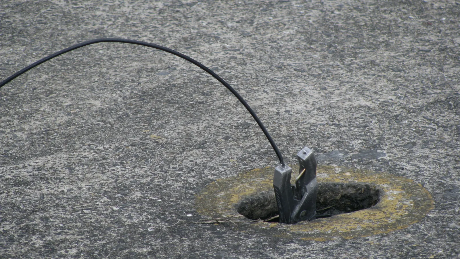
Static grounding during fuel loading is the practice of connecting the tank truck to the loading rack's grounding system. The electrostatic charge generated by flowing fuel then drains to earth before it builds up and sparks near fuel vapour. A grounding verification system adds a check that the connection is sound before loading can start.
This guide explains where the charge comes from, how bonding differs from grounding, what the verification system does at a bay and what a grounding assessment looks at. It builds on the interlock ideas in ESD, SIS and interlock and the zones in hazardous areas and Ex equipment.
Cause
Why flowing fuel builds up static charge
Static charge is what builds up when two surfaces rub or separate, like a balloon on hair. Fuel moving through a pipe does the same thing at the boundary between the liquid and the metal.
Charge separates at the pipe wall, at filters, valves and the nozzle, and the fuel leaves the hose carrying it.
Gasoline, diesel, kerosene and jet fuel conduct electricity poorly, so the charge fades slowly. Standards call such liquids static accumulators. In a truck compartment the charged liquid raises the voltage of its own surface. A spark can then jump between that surface and a conductive object such as a gauge probe or a loose metal item. The vapour space above the liquid may sit inside the flammable range, which is how a spark becomes a fire.
API RP 2003, NFPA 77 and IEC TS 60079-32-1 describe the controls. Grounding and bonding come first. Limiting flow velocity at the start of filling, until the outlet is covered, comes next, and so does keeping the outlet low in the compartment. Switch loading is a known high-risk case. A high-vapour-pressure product such as gasoline goes into a compartment that last carried a low-vapour-pressure product such as diesel, which can leave a flammable mixture above a charged liquid.
| Criterion | Top loading | Bottom loading |
|---|---|---|
| How fuel enters | Through a spout or fill pipe in the dome hatch | Through a coupler at the bottom of the truck |
| Static risk | Splashing and a long free fall raise charge and vapour | Fuel enters below the surface, so splashing is limited; charge still builds in the pipe, filter and liquid |
| Vapour at the hatch | Vapour leaves through the open hatch near the operator | Hatches stay closed; vapour goes to a recovery or vent line |
| Bonding and grounding | Clamp on the truck, and the spout bonded to the truck | Clamp on the truck; the coupler and arm bonded to the rack |
| Usual extra control | Slow start until the spout is submerged | Overfill probe permissive and slow start |
Terms
Bonding and grounding are different jobs
Bonding connects conductive objects to each other so they sit at the same electrical potential. At a bay these are the truck chassis, the loading arm, the rack piping and the gantry structure. With no voltage difference between them, no spark can jump from one to another.
Grounding, also called earthing, connects an object to the ground through the plant's earthing system. It gives the charge a path to leave. The loading rack is tied to the earth grid, so a clamp from the truck to the rack bonds and grounds the truck in one move.
A truck standing on rubber tyres is not reliably earthed. Dry tyres insulate, and the chassis can float at a voltage well above ground. That is why the clamp is required even when the truck is parked on a concrete apron next to a grounded rack. The same goes for a truck fresh from a workshop, whose chassis may be freshly painted so the old contact point is no longer bare.
Diagram
The path from product to earth
Charge is generated in the hose, filter and nozzle as fuel flows.
Hover, focus or tap a step to read its note.The verification unit is both a safety device and an interlock input. Without its OK signal the batch controller will not accept a preset, and if the signal drops during loading the valve closes. The exact reaction belongs in the safety requirements specification of the bay. Read how the controller handles permissives in the batch controller guide, and how the bay is laid out in the filling shed and loading rack guide.
Procedure
Steps at the bay
The sequence below is typical and follows the intent of API RP 2003 and NFPA 77. It does not replace the procedure of your terminal, which also covers wheel chocks, permits and the vapour recovery connection. A driver new to the terminal should be guided by the bay operator on the first loading, because the sequence differs slightly from one terminal to another.
Park and secure the truck
Engine off, brake set, wheels chocked as the site rule says.
Connect the clamp first
Bare metal on the chassis or tank, before any hatch or hose is opened.
Wait for the verification OK
Do not continue on a fault or a flashing lamp.
Connect the arm or open the dome
Only after the OK signal is on.
Start the batch slowly
Low flow until the outlet is covered, as the procedure says.
Watch the status
A lost connection stops the batch. Never reset it by bridging the signal.
Close, wait, disconnect
Close valves, disconnect the arm, and remove the clamp last.
Practice
Habits that lower charge before it forms
Grounding drains charge, but good habits reduce how much forms in the first place.
- Slow start. Begin at low flow until the fill pipe outlet is under the liquid, then raise the flow to the loading rate. This is why batch controllers use a two-stage preset.
- Low outlet. A fill pipe that reaches the bottom of the compartment limits splashing and free fall.
- Filters. Fine filters add charge, and the standards allow for the liquid to relax between the filter and the compartment. Keep the design the standard calls for when you replace a filter or a hose.
- Compartment history. Know what each compartment carried last. A TAS that records the product per compartment can flag a switch-loading risk at the order stage, so ask whether yours does.
- No loose metal. Gauge tapes, tools and floating items in a charged compartment are the objects a spark can jump to.
LPG is handled in closed systems, so the open hatch does not arise. A coupling leak still releases flammable vapour at the arm, which is why the truck and the filling arm keep the same bonding and grounding rules.
Failures
Where grounding fails in practice
Most grounding failures are small and human. The unit is rarely at fault on the first day. The ordinary wear of a busy bay opens the gap.
- Poor contact point. Paint, rust or a coated fitting gives a connection that reads open or, with a lax threshold, unreliable. Mark a bare, clean bonding point on each truck and teach drivers to use it.
- Cable and clamp wear. Cables are dragged, driven over and kinked. Broken strands inside intact insulation look fine and conduct poorly.
- A bridged signal. When trucks queue on a night shift, a faulty unit tempts operators to bridge the OK signal. Make bridging a recorded bypass with authorisation, and let the TAS show the bay as "grounding bypassed".
- A dead module nobody noticed. Modules age. The Balongan finding shows how long a protective device can sit unnoticed when it only ever reports OK. Routine functional tests find it.
None of these needs new technology. They need a test routine, a bypass rule and a clean contact point. Log every repair against the bay so the pattern of failures shows over time.
Data
What the control system should record
A grounding permissive that leaves no trace cannot be audited. The batch controller and the TAS can record what happened without extra hardware, as long as the signal reaches them.
Status at start
The state of the verification signal when each transaction begins.
Losses during loading
Each loss of the signal, with the time and the volume loaded at that moment.
Bypass events
Who bypassed the unit, why, and for how long.
Repeats per bay
Many short losses at one bay point to a worn clamp, cable or unit, not to drivers.
Review these records with the safety team on a fixed schedule. A bay with many short signal losses is telling you something about its clamp, and a bay with none for months may be reporting OK whatever happens. The CATALYST batch controller interface passes bay data to the terminal system, and INTEGRA TAS keeps a history for every transaction. Whether the grounding status lands in that record depends on how the signals are configured at your site.
Static grounding at the bay is not lightning protection and not stray current control, although API RP 2003 covers all three. The bay earthing is normally tied into the plant earthing network, and the electrode design and resistance targets come from the earthing design of the site, not from this article.
Assessment
What a grounding assessment checks
Citia carried out a grounding system assessment at the LPG terminal in Balongan, Indramayu, in 2026 under a batch controller scope. The technical field analysis reached four conclusions. The module was completely dead and had passed its ideal service life. Its reliability no longer met the working standard. A failed grounding system leaves static electricity that can cause fire and explosion.
The recommendation was to service the module: fit a temporary jumper for grounding while it is repaired, check the grounding module and check the module's power supply. A temporary jumper is a change to a safeguard, so record who fitted it, why, and when it must come off.
- Clamp and cable
- Jaws bite through paint and rust to bare metal; strands and insulation intact.
- Verification unit
- Lamps work, the unit reacts when the clamp is removed, and its self-test passes.
- Power supply to the unit
- Supply is present and stable. A dead supply must read as not grounded.
- Permissive wiring
- The OK signal reaches the batch controller or PLC, and losing it stops the batch.
- Bonding at arm and gantry
- Continuity between loading arm, piping and structure.
- Earth electrodes and grid
- Resistance to earth tested against the design value and compared with earlier records.
- Records
- Date, result, tester and the defects that were closed.
How often to check depends on the owner's procedure and the manufacturer's instructions. The usual pattern is a visual check of the clamp and cable at each loading. The verification unit gets a functional test on a fixed schedule, and the earthing system a test at a longer interval. Test again after a repair, a lightning strike or a change to the bay. Earlier results are the best comparison, because a slowly rising trend says more than a single passing value.
Terms used in this article
- Static electricity
- Electric charge that builds up when surfaces rub or separate, such as fuel against a pipe wall.
- Static accumulator
- A liquid that conducts poorly and so holds charge for a long time.
- Bonding
- Connecting conductive parts together so they share the same potential.
- Grounding (earthing)
- Connecting an object to the ground through an earthing system.
- Verification unit
- A monitor that proves the truck connection and gives an OK signal.
- Permissive
- A condition that must be true before an action, such as loading, is allowed.
- Splash loading
- Filling with the outlet above the liquid, which raises charge and vapour.
- Switch loading
- Putting a high-vapour-pressure product into a compartment that last held a low one.
- Relaxation time
- How long charge in a liquid takes to fade away.
Frequently asked questions
Why is grounding connected before opening the valve?
Because the charge starts building the moment fuel flows, and an unconnected truck has no path for it to leave. Connecting the clamp first, and confirming the verification OK, means the path exists before any fuel moves. The clamp also goes on before hatches or hoses are opened, so no spark can form while vapour is exposed.
What is the difference between bonding and grounding?
Bonding connects conductive objects to each other so they share the same potential, while grounding connects an object to earth. At a loading bay the clamp from the truck to the grounded rack does both. Bonding stops sparks between parts, and grounding drains the charge away.
How often should the grounding system be inspected?
The clamp and cable are checked at every loading, and the system on a schedule set by the owner's procedure and the manufacturer's instructions. There is no universal interval in the guidance. Test again after any repair, change or lightning strike, and keep the records.
Does bottom loading still need grounding?
Yes. Bottom loading reduces splashing and keeps hatches closed, but charge still builds in the pipe, filter and liquid. The truck still needs the clamp, and the arm or coupler still needs bonding to the rack.
Do rubber tyres ground a tank truck?
No. Dry rubber tyres insulate the chassis from the ground, so the truck can hold a charge even when it stands on a concrete apron. A clamp to the rack is the only dependable connection.
What does a grounding verification unit do?
It checks that the truck is actually connected to the rack's grounding system and gives an OK signal only while the connection is proven. The batch controller uses that signal as a permissive for loading. If the connection is lost, the signal drops and loading stops.
Sources and further reading
- API RP 2003 Protection Against Ignitions Arising Out of Static, Lightning, and Stray Currents, 8th edition (opens in a new tab)
- NFPA 77 Recommended Practice on Static Electricity (opens in a new tab)
- IEC TS 60079-32-1:2013 Explosive atmospheres, electrostatic hazards, guidance (opens in a new tab)
- Grounding system assessment at the LPG terminal in Balongan (opens in a new tab)
- Batch controller interface (opens in a new tab)
- Cover photo by Uploader; Vantey, public domain (opens in a new tab)
Next step
Prepare the technical discussion for your facility.
Bring the equipment list, diagrams and symptoms you have. The Citia team helps map the next step.
Related products and solutions
- KnowledgeFilling sheds and loading racks: how a tank truck is filledA filling shed is where tanker trucks are loaded through arms, meters and batch controllers. See the steps, top vs bottom loading and the safety checks.
- ProjectBalongan filling shed: grounding system assessmentBalongan filling shed grounding module is dead and past its service life; servicing is recommended because static electricity can cause fire and explosion.
- ProductCATALYST CT-BCConnects loading-bay batch controllers to the terminal system.
- ProductINTEGRA TASRuns truck loading at fuel and LPG terminals, from order and gate-in to filling and gate-out documents.
- KnowledgeESD vs SIS vs interlock, and what SIL meansEmergency shutdown (ESD) brings a process to a safe state; built to IEC 61511 with a target SIL, it becomes part of a safety instrumented system (SIS).
- KnowledgeHazardous areas and explosion-proof equipment: zones and Ex certificationHazardous areas are split into Zone 0, 1 and 2 by how often an explosive atmosphere appears; electrical equipment in them needs an Ex certificate that matches the zone.