
Control systems
PLC troubleshooting: safe steps from symptom to fix
Make the process safe, save the running program, then check power, CPU, I/O, wiring, communication and logic in that order. Symptom table and field cases.
- Topic
- Control systems
- Updated
- 13 November 2026
- Reading time
- 6 min
- Sections
- 7
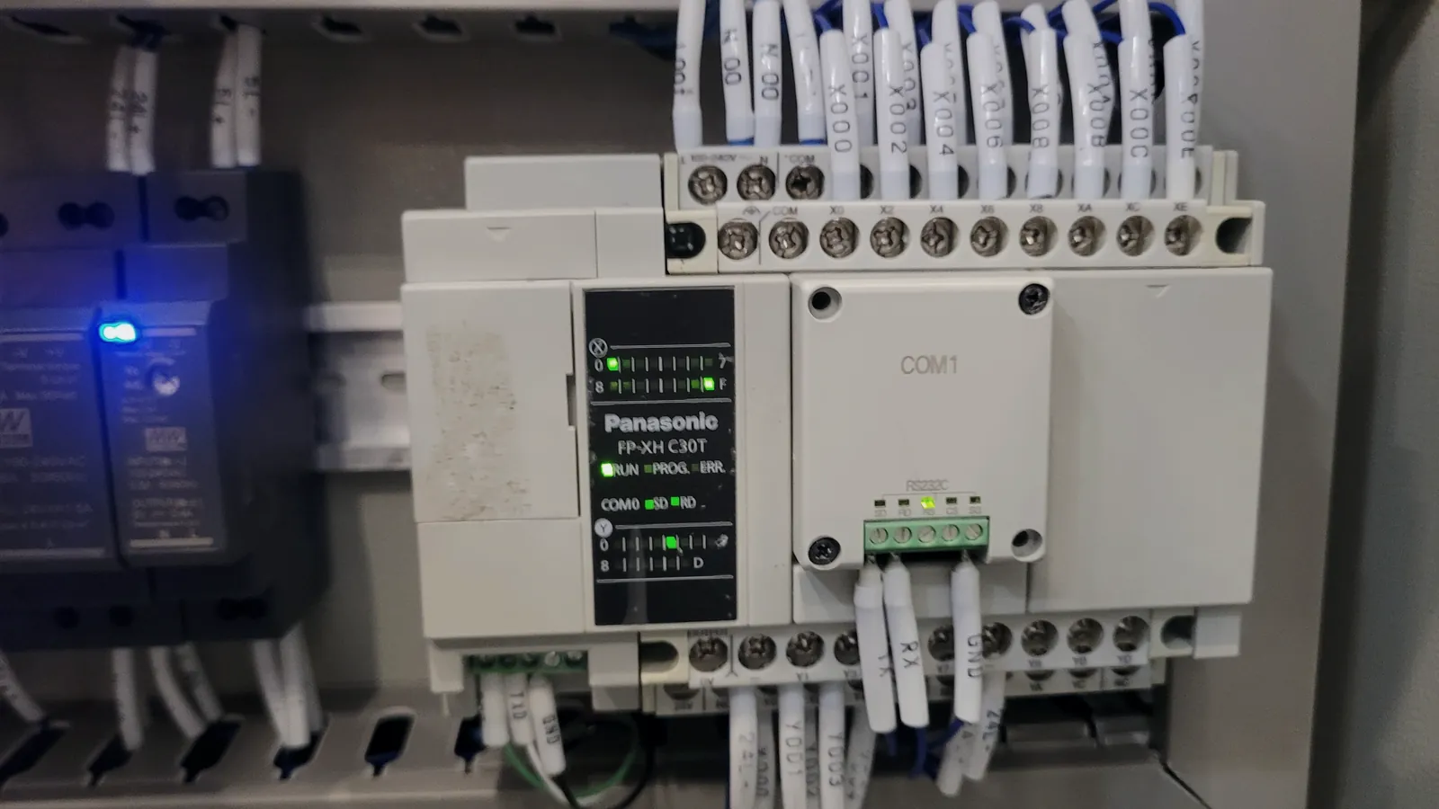
Safe PLC troubleshooting starts by making sure the process is safe and a backup of the running program exists, then checks in order: power supply, CPU status, I/O, field wiring, communication and, last, the program logic.
The order matters because most faults sit outside the program, and changing code on a running plant is the riskiest step of all. This guide follows that order with the symptoms technicians meet most often. For background on how a controller works, see what a PLC is; for how it connects to the control room, see the SCADA architecture guide.
Safety first
Make it safe before you touch anything
A PLC fault is a process problem before it is an electronics problem. The first job is to know what the equipment is doing now and what it will do when you intervene.
Agree the work with operations and follow the site permit. Find out which outputs the PLC drives and what happens if they switch: a pump that starts, a valve that closes, a shutdown that trips. If equipment must be isolated, isolate it physically, not only in software.
Then preserve the evidence. Photograph the LED states, read the CPU diagnostic buffer or fault log, and note the time of the first symptom. Upload and save the program that is actually running before connecting anything else. A reset or power cycle clears much of this information, and a fault that disappears after a restart usually returns.
The same order applies to Allen-Bradley, Siemens, ABB and other brands. What changes is where the diagnostics are read, for example the module status pages in the vendor's engineering software or the fault codes listed in the hardware manual.
Method
The safe order of checks
Check the simplest and most likely causes first, and leave the program for last. The sequence on the right follows the path of a signal through the panel.
Power comes first because a sagging 24 VDC supply produces strange symptoms everywhere. CPU status tells you whether the controller is running, stopped or faulted. I/O module diagnostics show whether a card has failed or lost its power. Field wiring and devices are where most physical faults live. Communication comes next, because a healthy PLC can still look dead to SCADA.
Only when every layer below checks out does the logic deserve suspicion. Even then, the program usually did what it was written to do; the question is whether the conditions it saw were the real ones.
Power supply
Measure supply voltages, check fuses, breakers and UPS.
CPU status
Run, stop or fault LEDs; read the diagnostic buffer.
I/O modules
Module diagnostics, channel LEDs, module power.
Field wiring and devices
Terminals, cables, relays, sensors and actuators.
Communication
Ports, cables, switches, gateways, addresses.
Program logic
Online status of the rungs or blocks involved.
Symptoms
Common symptoms and where to look
Most PLC calls start with one of a handful of symptoms. Each one points to a short list of likely causes and a first test.
The table is a starting point drawn from common practice, not a vendor procedure. The vendor manual for the exact CPU and module model always takes precedence, especially for the meaning of LED patterns and fault codes.
Write down each test and its result as you go, with the time. A short log turns a one-off repair into knowledge the next shift can use, and it shows which causes have already been ruled out when the fault comes back at night.
| Criterion | Likely causes | First test |
|---|---|---|
| CPU fault or stop LED | Program error, watchdog, failed module, flat CPU battery | Read the diagnostic buffer before any reset |
| Output LED on, device not moving | Blown fuse, failed relay, broken wire, faulty device | Measure voltage at the output terminal and at the device |
| Input not seen by the PLC | Sensor fault, wiring, missing common, wrong address | Operate the sensor and watch the input LED and online value |
| Analog value frozen or at its limit | Open loop, transmitter fault, channel fault, scaling | Measure loop current; inject a test signal |
| Communication drops in and out | Loose connector, surge damage, converter, address or baud mismatch | Trace the chain link by link |
| PLC stops after a power dip | No UPS, weak supply, retentive data lost | Check supply hold-up and UPS transfer |
Outputs
Output LED on, but nothing moves
This is the most common output complaint, and the LED is the reason it confuses people. The LED shows what the logic is asking for, not what reaches the field.
Work outward from the module. Measure the voltage at the output terminal with the output on. If it is missing, suspect the output channel, the module supply or a fuse on the module. If it is present, follow the circuit through any interposing relay, the field terminals and the cable to the device, measuring at each point. A coil that measures correctly but does not pull in points to the device itself.
At the Cikampek fuel terminal, Citia troubleshot a faulty Allen-Bradley digital output by checking the wiring and the I/O function before replacing the failed component, then replaced the Moxa NPort 5160 meter-reading gateway and retested with the existing system. The lesson recorded was that a full check of I/O, wiring, communication settings and network finds the real source and keeps the replacement from disturbing the rest. See the Allen-Bradley output module work.
Communication
Communication that drops in and out
Intermittent communication is the slowest fault to find because it is often fine while you are watching. The cure is to treat the path as a chain and test each link.
At PT Bio Farma in Bandung, the electrical SCADA reads power meters through ABB AC500 PLC masters, Modbus gateways and RS-485 multidrop networks. Citia's checks covered the whole chain from SCADA server through industrial Ethernet and PLC master to the meters, including lost communication, invalid data, unreachable devices and mismatches between field and SCADA, plus a direct engineering-laptop connection for diagnostics. See the ABB AC500 troubleshooting.
Physical damage is a frequent cause. On the Balongan PressMon pipeline network, degraded fibre optic converters caused intermittent loss and delayed data. On the Jambi MOV link, a surge protection device guards the RS-485 line and a LAN arrester guards the Ethernet side, because surges from lightning or switching can damage ports long before anyone sees a cable fault.
Configuration mismatches cause much of the rest. After a device or gateway is replaced, its address, baud rate, parity and register map must match what the master expects. At Eltech in Bekasi, Modbus addressing and IP settings had to be aligned before the central SCADA read busbar values correctly; see the Eltech integration.
Meter, MOV or drive: address, baud rate, power.
Hover, focus or tap a step to read its note.Program changes
Before you change the program
Change the program only after the fault is proven to be in the logic. Most of the time it is not.
At the Lomanis fuel terminal, a flowmeter gave no reading on the DCS screen. Signal tracing and injection showed the I/O modules were healthy and the fault sat in the flowmeter and totalizer controller. Proving that first avoided changes to a system that was working.
When a change is needed, compare the online program with the saved copy, record what will change and why, and agree a test with operations. Check the firmware and software versions too. At Petrokimia Gresik, the existing backup could not be downloaded because the controller firmware had been upgraded, so a newer ABB Freelance version had to be installed on the engineering station. Save the new version straight after the change.
Next step
Repair, replace a module or escalate
Replace a module when the diagnosis points to it, not to see whether the fault moves. Swapping parts at random hides the cause and uses up spares.
If the fault follows power dips, the fix may sit in the power system rather than the PLC. At the Donggala depot, UPS units and automatic transfer switches were added so the SIS and process control panels keep running while supply changes between PLN and the generator set.
Before fitting a spare, check that its catalogue number, hardware revision and firmware match what the program expects. A module that is no longer sold may still be available only as a repaired spare, which is a sign to start planning; the options are compared in repairing or migrating obsolete PLC and SCADA. Keep the configuration and program copies current as described in PLC and SCADA backups you can restore.
Faults that keep returning, or that move between devices, deserve a structured look across all layers. The PLC/SCADA assessment guide explains what to prepare, and Citia's Condition Monitoring and Maintenance service covers scheduled checks, alarm analysis and backup tests.
Terms to know
- Force
- Overriding an input or output value from the engineering software, regardless of the real signal or the logic.
- Online edit
- Changing the program while the PLC keeps running.
- Diagnostic buffer
- The CPU's log of faults and events, with times, used to find what happened first.
- Watchdog
- A timer that stops the CPU if a scan takes too long.
- Interposing relay
- A relay between a PLC output and a field device that needs a different voltage or current.
- Multidrop
- Several devices sharing one RS-485 cable, each with its own address.
- Signal injection
- Feeding a known test signal into a channel to prove whether the module and wiring work.
Frequently asked questions
Why is a PLC output not working when its LED is on?
A PLC output LED shows that the logic has switched the output on, not that power reached the device. Measure at the output terminal, then follow the circuit through fuses, interposing relays and field wiring to the device.
What should be done before changing a PLC program?
Before changing a PLC program, upload and save the running program, confirm the firmware and software versions, prove the fault is in the logic and agree the change and its test with operations. Save the new version immediately afterwards.
When does a PLC I/O module need replacing?
A PLC I/O module needs replacing when its diagnostics or a signal injection test show the channel or module has failed while power and wiring are good. Check the spare's catalogue number, revision and firmware first.
How do you fix PLC communication that keeps dropping?
Fix intermittent PLC communication by tracing the chain link by link: device settings, RS-485 wiring and termination, surge protection, gateways and converters, switches and the SCADA driver log. Physical damage from surges and degraded converters is a frequent cause.
How do you troubleshoot an ABB AC500 PLC?
Troubleshooting an ABB AC500 starts with the status of the CPU and communication modules, then the links between PLC masters, gateways and field devices. A direct engineering-laptop connection gives the diagnostics; the vendor manual explains each status code.
What does PLC maintenance include?
PLC maintenance includes checking power supplies and UPS, CPU and module diagnostics, terminals and wiring, communication health and alarms, plus keeping tested backups of programs and configurations. Findings are ranked so urgent items are fixed first.
Sources and further reading
- NIST SP 800-82 Rev. 3: Guide to Operational Technology (OT) Security (opens in a new tab)
- Primary Mitigations to Reduce Cyber Threats to Operational Technology (opens in a new tab)
- ABB PLC troubleshooting (opens in a new tab)
- Supply of Allen-Bradley PLC digital output modules and Moxa converter (opens in a new tab)
- Petrokimia Gresik: ABB PLC repair (opens in a new tab)
- PLC/SCADA assessment: start with symptoms, topology and backups (opens in a new tab)
- Cover photo by Angga Panca Alam Anugrah, CC BY-SA 4.0 (cropped and colour graded) (opens in a new tab)
Next step
Prepare the technical discussion for your facility.
Bring the equipment list, diagrams and symptoms you have. The Citia team helps map the next step.
Related products and solutions
- KnowledgeWhat is a PLC? How it works, types and where it is usedA PLC reads inputs, runs logic in a repeating scan and drives outputs. How the scan works, what is in a PLC panel, the languages and the main types.
- KnowledgeTroubleshooting Modbus RS-485 communicationMost Modbus RS-485 faults start at the physical layer. A field checklist for termination, biasing, topology, grounding, serial settings and exception codes.
- KnowledgePLC and SCADA backups you can actually restoreA backup counts only if it matches the running system, includes configs, licences and software versions, and has passed a restore test. Checklist and schedule.
- KnowledgePLC/SCADA assessment: start with symptoms, topology and backupsSeparate equipment, communications, applications and operating processes before deciding on replacement.
- ProjectABB PLC troubleshootingTroubleshooting and recovery of the electrical SCADA at PT Bio Farma in Bandung. The system runs on ABB AC500 PLCs and watches power distribution across the site's buildings, substations, power house and generators.
- ProjectSupply of Allen-Bradley PLC digital output modules and Moxa converterTroubleshooting and replacement of a faulty Allen-Bradley PLC digital output and a Moxa NPort 5160 meter reading gateway at the Cikampek fuel terminal.
- ProjectPetrokimia Gresik: ABB PLC repairRepair, recovery and re-programming of the ABB AC 800F and Freelance control system that monitors the 6 kV and 20 kV switchgear in the coal unit at PT Petrokimia Gresik.
- ProjectVSD system optimizationCitia restored distribution pump and VSD operation in 2022 by moving their control from a central Allen-Bradley PLC to a dedicated Siemens S7-1200 panel.
- ProductCondition Monitoring & MaintenanceKeeps TAS, PLC, SCADA, servers, gateways and networks healthy, with backups you can restore.