
Terminal Operations
Terminal Automation System (TAS): what it is, its components and how it works
A terminal automation system (TAS) runs fuel and LPG truck loading, from order and gate-in to metering, delivery documents and gate-out.
- Topic
- Terminal Operations
- Updated
- 13 November 2026
- Reading time
- 5 min
- Sections
- 7
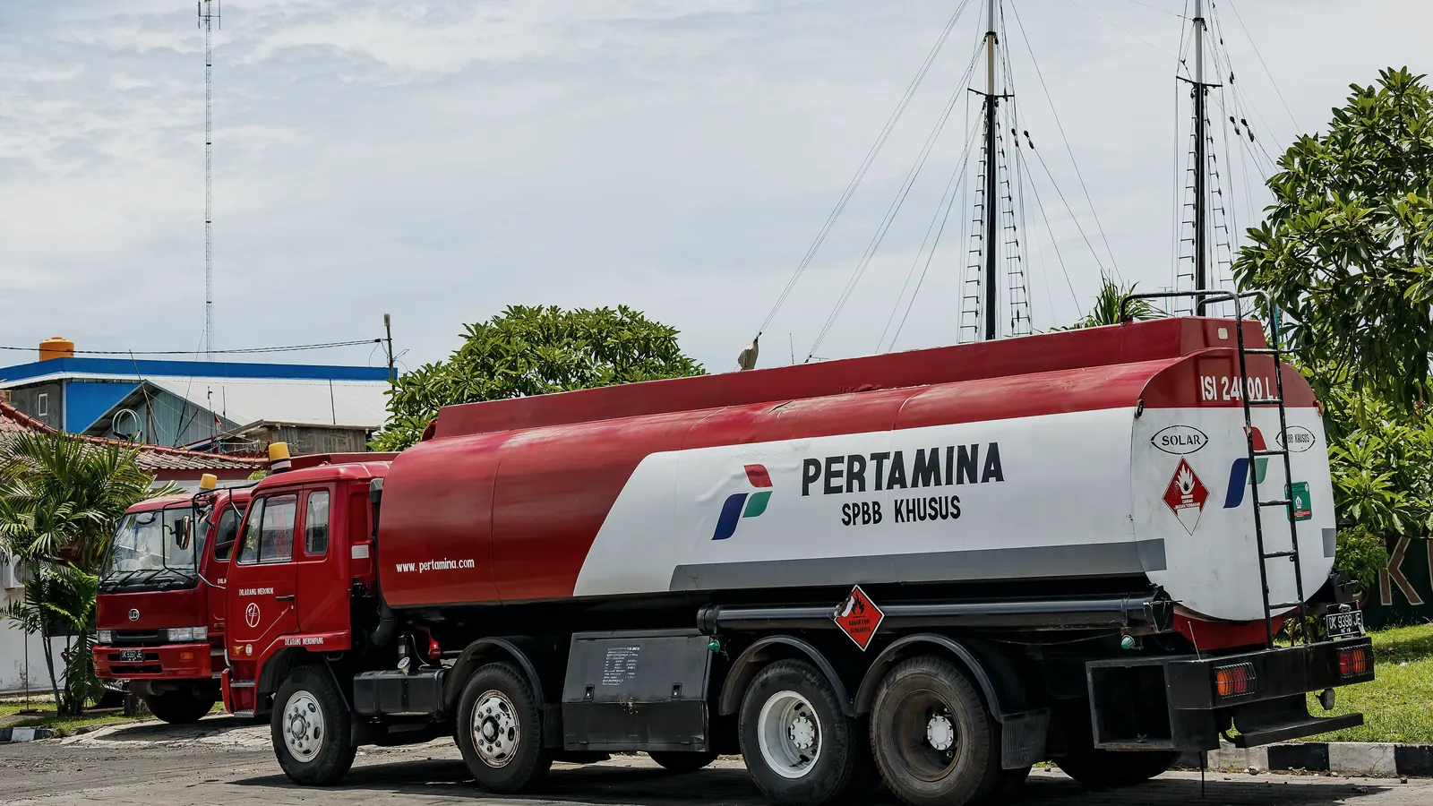
A terminal automation system (TAS) is the software and control system that runs fuel or LPG dispatch at a terminal, from the order and gate-in through loading authorization and volume measurement to the delivery documents and gate-out.
In Indonesia the term usually refers to the system inside a TBBM (Terminal Bahan Bakar Minyak) or an LPG depot. The TAS decides which truck may load, which product goes into which compartment, and how much. It then closes each transaction with the measured volume and passes the result to the business system. This guide explains the parts of a TAS, how an order moves through it, and what to check before you buy, upgrade or maintain one.
Function
What a TAS does at a fuel terminal
A TAS makes sure the right truck receives the right product in the right quantity, and that every litre is recorded. Without it, the same work runs on paper delivery orders, radio calls and manual entries at each bay.
For an engineer, the TAS is the transaction layer of the terminal. It holds the master data (customers, products, vehicles, drivers, compartments), validates every request against that data, and sends presets and permissives down to the bay. When the batch ends, it collects the metered volume, prints the delivery note and posts the result upward. The Citia product page for INTEGRA TAS lists the same chain: gate check, queue, loading authorization, the filling transaction at the bay and the delivery documents at gate-out.
Orders and master data
Receives shipment or loading orders and checks them against products, vehicles and drivers.
Gate-in and gate-out
Identifies the truck at the gate, usually with an RFID card, and records entry and exit times.
Queue and bay assignment
Puts trucks in a queue and assigns a bay that has the ordered product.
Loading authorization
Sends the preset volume and permissives to the batch controller or PLC at the bay.
Metered results
Collects the measured volume per compartment and closes the transaction.
Documents and posting
Prints delivery documents and sends results to SAP or another ERP.
Workflow
How a loading order moves through the terminal
Every truck that loads fuel follows the same basic path, and the TAS records each step. The diagram below shows that path from the enterprise order to the posting that closes it.
The sequence matters because each step checks the one before it. A truck cannot be called to a bay before gate-in. A bay cannot start before the TAS has sent a preset. The truck cannot leave before the transaction is closed and the documents are printed. At Pertamina terminals the order usually arrives from the distribution system (SIOD at the sites Citia supports) and results go back to SAP, as described in the Jambi terminal automation project.
Shipment or loading order from the ERP or distribution system.
Hover, focus or tap a step to read its note.Components
TAS components, layer by layer
A TAS is not one box. It is a chain of devices and programs that sit in four layers, and each layer fails in its own way.
- Field layer. Flow meters, control valves, RFID readers, grounding units, overfill sensors and the loading arms themselves.
- Control layer. Batch controllers and the PLC that runs pumps, valves and interlocks at each bay.
- Application layer. The TAS server and workstations, the gate application and, alongside it, the TMS for tank stock.
- Enterprise layer. SAP or another ERP, plus the distribution order system.
The ISA-95 standard (IEC 62264) describes the same split for plants in general, with five levels from the physical process (Level 0) to business planning (Level 4). The Citia Integrated TAS Portfolio follows this chain: RFID and gate, a Siemens S7-300 PLC, WebAccess SCADA, INTEGRA TAS and TMS, then SAP and SIOD.
- Field
- Meters, valves, RFID, grounding, overfill sensors
- Control
- Batch controller, PLC, interlocks
- Application
- TAS server, gate PC, TMS
- Enterprise
- SAP or ERP, order system
Comparison
Manual operation compared with a TAS
| Criterion | Manual or semi-manual | With a TAS |
|---|---|---|
| Truck identification | Paper DO and visual check at the gate | RFID card linked to vehicle, driver and order |
| Loading quantity | Operator sets the volume at the bay | TAS sends the preset; the bay cannot exceed it |
| Recording | Hand-written or typed after the fact | Metered volume captured per compartment |
| Documents | Prepared separately from the measurement | Printed from the closed transaction |
| ERP update | Batch entry at end of shift | Posted per transaction or per batch interface |
| Audit trail | Depends on log books | History kept for every transaction |
The difference that matters most is where the number comes from. In a manual terminal, the delivery document and the meter reading are two separate records that someone has to reconcile. In a TAS they are the same record, so a mismatch shows up immediately instead of at month end.
A TAS does not replace the people. Dispatchers still handle exceptions, and the shift supervisor still approves corrections. What changes is that every correction leaves a trace with a name and a time.
Metering
Where the loaded volume comes from
The volume on the delivery note is measured by the meter and batch controller at the bay; the TAS only receives and stores it. So the accuracy of a TAS transaction is the accuracy of the measuring system underneath it.
The international reference is OIML R 117-1:2019, *Dynamic measuring systems for liquids other than water*. It sorts measuring systems into four accuracy classes and sets the maximum permissible error for each. For loading-rack metering, API MPMS Chapter 6.2A (2021) covers truck and rail loading measurement systems. In Indonesia, meters used for trade also fall under legal metrology checks by the metrology authority, so verification records belong in the TAS project file, not only in the maintenance cabinet.
- 4accuracy classes for liquid measuring systemsOIML R 117-1:2019, Table 2
- 0.5%maximum permissible error, class 0.5 systemOIML R 117-1:2019, Table 3, line A
- 5levels in the ISA-95 model, Level 0 to Level 4ISA-95 / IEC 62264
Resilience
What happens when the TAS network fails
A good TAS keeps the bay safe and the record complete even when the server or network drops in the middle of a loading. That only happens if the design decides, in advance, which layer owns which decision.
In practice the preset and the permissives already sit in the batch controller and the PLC once a batch starts. If the link to the TAS breaks, the bay can finish or stop the running batch on its own, and the controller keeps the metered volume until the TAS reads it again.
What must not happen is a new batch starting without TAS authorization. Ask how the system reconciles a batch that finished while the server was down, and who approves that reconciliation. The TAS, TMS and TPS article explains why each system needs its own data boundary.
Field notes
From the field: TAS work at Pertamina terminals
Most TAS problems at running terminals are integration and maintenance problems, not missing features. Citia's project records show the same pattern across sites.
- At the Jambi fuel terminal, the TAS ties shipment, gate-in, the filling shed and gate-out to SAP, SIOD, RFID, meters, the meter user interface (MUI) and pump control, with LTSA support for monitoring and troubleshooting.
- At Padalarang, the support contract covers the FDM and FD-Flow applications, the TAS server, the gate interface PC and the NFC readers, with a database backup during each monthly visit.
- The Pulau Layang scope adds SCADA, electrical systems and safety equipment such as motor-operated valves and emergency shutdown valves.
The lesson repeated in these records is that the boundary of responsibility must be written down. When a printer, a network switch or a meter outside the contract fails, the TAS is usually blamed first.
Typical phases of a TAS project
- Phase 1
Site survey
List bays, meters, controllers, gates and the documents the terminal must produce.
- Phase 2
Design and interfaces
Fix data boundaries with the ERP, TMS and field devices.
- Phase 3
Factory acceptance test
Run the software and panels against simulated field signals.
- Phase 4
Installation and SAT
Install bay by bay and test each one with real trucks.
- Phase 5
Operation and LTSA
Monitoring, backups, troubleshooting and changes such as new products.
Changes after go-live are part of the life of a TAS. When Biosolar B50 replaced B40, the product and material codes in the FD-Flow application at Padalarang had to be reconfigured and test transactions run before operation, as recorded in the B50 product update project. Plan for that kind of change in the support contract from the start.
For the cloud direction, Citia's INTEGRA CTP is in development: workflows run in the cloud while PLC control and safety permissives stay in the local control system.
Terms used in this article
- TAS (terminal automation system)
- Software and control system that runs truck loading at a terminal, from order to gate-out.
- TMS (tank management system)
- System that reads tank gauges and turns levels into stock, history and tank tickets.
- Batch controller
- Controller at the bay that opens the valve, counts meter pulses and stops at the preset volume.
- Bay
- One loading position under the gantry, with its own arms, meters and controller.
- Gantry
- The steel structure and canopy that hold the loading arms over the truck.
- DO (delivery order)
- The order that says which product and how much a truck may load.
- Tank ticket
- A record of tank level, temperature and volume at a point in time, used for stock and transfers.
- Preset
- The volume the TAS authorizes for one compartment or batch.
Frequently asked questions
What is the difference between a TAS and a TMS?
A TAS manages truck loading transactions, while a TMS manages tank measurements and stock. The TAS asks whether a truck may load and how much; the TMS tells you how much product is in each tank. They exchange data but answer different questions.
Which field devices connect to a terminal automation system?
The usual field devices are flow meters, batch controllers, control valves, RFID readers, grounding units and overfill sensors, plus the PLC that runs pumps and interlocks. Most of them reach the TAS through the batch controller or the PLC rather than directly.
Can a TAS be connected to SAP?
Yes, a TAS is normally connected to SAP or another ERP to receive orders and send back loaded volumes and status. The interface needs agreed message formats, a retry rule for failed postings and a clear owner for corrections.
What happens if the TAS network goes down during loading?
In a well-designed system the running batch finishes or stops safely at the bay, because the preset and permissives already sit in the batch controller and PLC. No new batch should start until the TAS is back, and the stored volume is reconciled afterwards.
How long does a TAS implementation take?
Implementation time depends on the number of bays, the state of existing field devices and the number of interfaces. A realistic plan counts survey, design, factory test, bay-by-bay installation and site testing, while the terminal keeps operating.
Does a TAS make metering more accurate?
No, a TAS does not change meter accuracy; it removes transcription errors. Accuracy comes from the meter, the batch controller and their verification under rules such as OIML R 117-1:2019.
Sources and further reading
- OIML R 117-1:2019 Dynamic measuring systems for liquids other than water, Part 1 (opens in a new tab)
- API MPMS Chapter 6.2A: Metering Assemblies, Truck and Rail Loading and Unloading Measurement Systems (opens in a new tab)
- ISA-95 Standard: Enterprise-Control System Integration (opens in a new tab)
- IEC 62381:2024 Automation systems in the process industry: FAT, SAT and SIT (opens in a new tab)
- INTEGRA TAS product page (opens in a new tab)
- Fuel Terminal Jambi distribution workflow (opens in a new tab)
- Cover photo by CEphoto, Uwe Aranas, CC BY-SA 3.0 (cropped and colour graded) (opens in a new tab)
Next step
Prepare the technical discussion for your facility.
Bring the equipment list, diagrams and symptoms you have. The Citia team helps map the next step.
Related products and solutions
- KnowledgeTerminal automation system architecture: field, control, application and enterprise layersTAS architecture has four layers, from field devices to ERP. See how they connect, what fails at each layer, where redundancy pays and how to segment the network.
- KnowledgeFilling sheds and loading racks: how a tank truck is filledA filling shed is where tanker trucks are loaded through arms, meters and batch controllers. See the steps, top vs bottom loading and the safety checks.
- KnowledgeWhat is a tank management system? From level readings to tank tickets and stockA tank management system (TMS) collects ATG data from every tank, calculates standard volume, records stock movements and issues tank tickets.
- ProductINTEGRA TASRuns truck loading at fuel and LPG terminals, from order and gate-in to filling and gate-out documents.
- ProductIntegrated TAS PortfolioTAS as one engineered platform: loading, gates, monitoring, maintenance and enterprise links.
- KnowledgeTAS, TMS and TPS Integration: what does each system manage?Separate distribution processes, inventory measurements and document reporting before defining integration.
- ProjectFuel Terminal Jambi distribution workflowTAS, device integration and LTSA support
- ProjectPadalarang TAS lifecycle supportDistribution TAS maintenance and troubleshooting
- WebinarReliable terminals: TAS and control system reliabilityCitia Micro Webinar material examines terminal operations, field devices, controls, applications and fault diagnosis.