
Truck Loading
Filling sheds and loading racks: how a tank truck is filled
A filling shed is where tanker trucks are loaded through arms, meters and batch controllers. See the steps, top vs bottom loading and the safety checks.
- Topic
- Truck Loading
- Updated
- 13 November 2026
- Reading time
- 3 min
- Sections
- 6
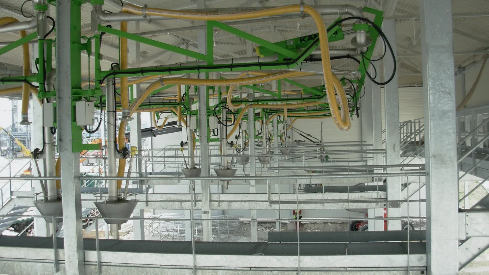
A filling shed is the covered area in a fuel terminal where tanker trucks are filled with fuel through loading arms, with the volume measured by a flow meter and controlled by a batch controller according to the order.
The English terms truck loading rack, loading bay and gantry all describe parts of the same place. Each bay is one loading position, and its equipment reports to the terminal automation system (TAS) described on the INTEGRA TAS product page. This article walks through one loading from arrival to departure and explains the checks that keep it safe and accurate.
Equipment
What sits in one loading bay
One bay is a small measuring station. Fuel comes from the tank through a pump header, passes a meter and a control valve, and leaves through the arm into one compartment at a time.
The batch controller is the brain of the bay. It receives the preset, opens the valve in stages, counts the meter pulses and closes the valve when the preset is reached. Around it sit the safety devices: a grounding unit that proves the truck is bonded, an overfill sensor connection that trips when a compartment is nearly full, and an emergency stop. API MPMS Chapter 6.2A (2021) is the API reference for truck and rail loading measurement systems such as these.
- Arm
- Top or bottom loading arm
- Meter
- Flow meter with pulse output
- Valve
- Two-stage control valve
- Controller
- Batch controller or PLC
- Safety
- Grounding, overfill, emergency stop
- ID
- RFID or card reader
Procedure
The loading sequence, step by step
Every loading follows the same order of steps, and each step is a condition for the next. Skipping one is the most common root cause of loading incidents.
Position the truck
Driver stops at the marked bay, engine off, brakes on, wheel chocks in place.
Connect grounding
Clamp the grounding cable and wait for the unit to confirm a good bond.
Connect arm and sensors
Couple the arm to the compartment and plug in the overfill sensor cable.
Authorize
Card or RFID read; the TAS sends the product and preset for each compartment.
Fill
Valve opens at low flow, steps up to full flow, then drops to low flow before the preset.
Stop and close
Valve closes at the preset; the controller records the metered volume.
Disconnect and leave
Arm, sensor and grounding removed; documents printed; truck released.
Methods
Top loading compared with bottom loading
Top loading fills the compartment through the hatch on the roof of the tank; bottom loading fills it through a coupling at the bottom. Both are still in use, often in the same terminal.
Bottom loading keeps the operator at ground level and lets vapour return through a separate hose, which is why new installations tend to use it. Top loading needs a platform and fall protection, and the arm must reach the bottom of the compartment to limit splashing. The choice also decides the truck fleet: a bottom-loading bay only serves trucks fitted with matching adapters and an overfill sensor socket.
| Criterion | Top loading | Bottom loading |
|---|---|---|
| Connection point | Hatch on the tank roof | Coupling at the bottom of the compartment |
| Operator position | On a platform at height | At ground level |
| Vapour | Escapes through the open hatch unless captured | Returned through a vapour hose |
| Static and splashing | Arm must reach the bottom to limit splashing | Product enters from below, less free fall |
| Truck requirement | Open hatch access | Matching adapters and overfill socket |
Safety
Why grounding comes before the first litre
Flowing fuel builds up static charge, and grounding gives that charge a safe path to earth before a spark can form. That is why the batch controller will not open the valve until the grounding unit confirms the bond.
A grounding unit that has failed is worse than one that is missing, because operators trust its green light. In a grounding system assessment at the Balongan LPG facility, Citia found the grounding module completely dead and past its ideal service life. The report notes that a failed grounding system leaves static electricity that can cause fire and explosion, and recommended a temporary jumper while the module and its power supply were checked and repaired.
Permissives
What stops a loading automatically
A loading runs only while every safety signal says yes. These signals are called permissives, and losing any one of them closes the valve.
The batch controller or the bay PLC watches them continuously. A typical set is grounding healthy, overfill sensor dry, emergency stop released, arm in position and a valid preset from the TAS. The Endress+Hauser RA33 technical information shows the same pattern for filling a tank truck: two-stage valve control, with an automatic after-run correction so the valve closes early enough to hit the preset.
Grounding unit confirms the truck is bonded.
Hover, focus or tap a step to read its note.Field notes
From the field: meters 5 and 6 at Jambi
Adding meters to a running filling shed is mostly cabling, mapping and testing. Citia's integration of meters 5 and 6 at the Pertamina Jambi fuel terminal followed that order.
The team installed a meter user interface (MUI) at each filling bay, added a PLC I/O module to take the pump demand signal, and placed a junction box panel for cable termination. Meter data was then mapped into the CS Flow application, cables were pulled and checked for continuity, and every device was function-tested at commissioning. The wider Jambi terminal automation project shows where those bays fit in the full gate-to-gate workflow.
Terms used in this article
- Filling shed
- Covered loading area where tanker trucks are filled.
- Loading rack
- The arms, meters, valves and controller at one bay.
- Loading arm
- Swivel pipe that carries fuel from the rack into the truck.
- Bottom loading
- Filling through a coupling at the bottom of each compartment.
- Top loading
- Filling through the hatch on top of the tank.
- Grounding
- Bonding the truck to earth so static charge can drain safely.
- Permissive
- A safety signal that must be true before and during loading.
- MUI
- Meter user interface, the operator screen at a bay.
Frequently asked questions
What is the difference between top loading and bottom loading?
Top loading fills through the hatch on the tank roof, while bottom loading fills through a coupling under the tank. Bottom loading keeps the operator on the ground and returns vapour through a hose.
Why is grounding connected before filling a tanker truck?
Grounding is connected first so that static charge from flowing fuel drains to earth instead of sparking. The batch controller normally refuses to open the valve until the grounding unit confirms the bond.
What stops an automatic loading?
An automatic loading stops when the preset is reached or when any permissive is lost. Typical permissives are grounding, the overfill sensor, the emergency stop, arm position and a valid TAS authorization.
How long does it take to fill one tanker truck?
The time to fill a tanker truck depends on compartment size, the flow rate the meter and arm allow, and the low-flow phases at start and stop. Waiting at the gate and the bay often takes longer than the filling itself.
What is a loading rack?
A loading rack is the set of arms, meters, valves and controllers that fills trucks at one bay. Several racks sit under one filling shed or gantry.
Sources and further reading
- API MPMS Chapter 6.2A: Metering Assemblies, Truck and Rail Loading and Unloading Measurement Systems (opens in a new tab)
- OIML R 117-1:2019 Dynamic measuring systems for liquids other than water, Part 1 (opens in a new tab)
- Technical Information RA33 Batch Controller (TI00163K) (opens in a new tab)
- Grounding system assessment, LPG Balongan (opens in a new tab)
- Pertamina Jambi Terminal: integration of meters 5 and 6 (opens in a new tab)
- Cover photo by Kanon Loading Equipment B.V, CC BY-SA 3.0 (cropped and colour graded) (opens in a new tab)
Next step
Prepare the technical discussion for your facility.
Bring the equipment list, diagrams and symptoms you have. The Citia team helps map the next step.
Related products and solutions
- KnowledgeBatch controllers in truck loading: function, operation and TAS integrationA batch controller loads a preset volume at the bay, stages the valve and stops on time. See how it works, how it links to a TAS and why batches overrun.
- KnowledgeStatic grounding during fuel loadingGrounding a tank truck during loading drains the static charge that fuel flow builds up, so no spark forms near vapour; a verification unit blocks loading until the connection is proven.
- KnowledgeFlowmeters for fuel: types, working principles and how to chooseFuel flowmeters measure volume or mass; PD, turbine and Coriolis are the usual choices at a loading bay. Compare principles, accuracy classes and selection.
- ProductCATALYST CT-BCConnects loading-bay batch controllers to the terminal system.
- ProductINTEGRA TASRuns truck loading at fuel and LPG terminals, from order and gate-in to filling and gate-out documents.
- ProjectPertamina Jambi Terminal: integration of meters 5 and 6Citia integrated Meter 5 and Meter 6 into the CS Flow application at the Pertamina Jambi Fuel Terminal filling shed, from MUI and PLC I/O to commissioning.
- ProjectBalongan filling shed: grounding system assessmentBalongan filling shed grounding module is dead and past its service life; servicing is recommended because static electricity can cause fire and explosion.
- ProjectFuel Terminal Jambi distribution workflowTAS, device integration and LTSA support