
Truck Loading
Batch controllers in truck loading: function, operation and TAS integration
A batch controller loads a preset volume at the bay, stages the valve and stops on time. See how it works, how it links to a TAS and why batches overrun.
- Topic
- Truck Loading
- Updated
- 13 November 2026
- Reading time
- 4 min
- Sections
- 6
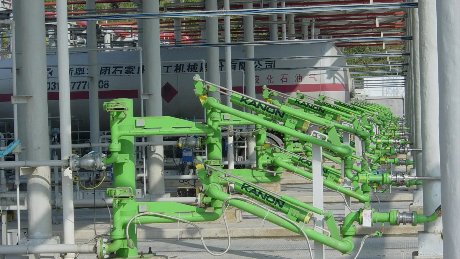
A batch controller is the controller at a loading bay that receives the ordered volume, opens and closes the valve, reads the flow meter pulses, and stops the loading exactly at the authorized volume.
You will also hear it called a preset controller or preset counter. It sits between the meter and valve on one side and the terminal automation system on the other. How the TAS divides work with the tank and reporting systems is covered in the Citia article on TAS, TMS and TPS boundaries; this article stays at the bay.
Function
What a batch controller does
In plain terms, a batch controller turns an order into a measured, stopped flow. It does the counting that an operator with a stopwatch and a valve handle used to do, and it does it the same way every time.
The Endress+Hauser RA33 technical information (2025) lists the functions that most controllers share: valve control for single-stage and two-stage filling, automatic after-run correction, temperature and density compensation according to ASTM D1250-04, a batch report for every run, and remote start and abort. Terminal-grade controllers such as the Emerson DL8000 add additive injection and blending of up to four products.
Preset
Holds the authorized volume for one compartment.
Valve staging
Low flow at start and end, full flow in between.
Pulse counting
Totalizes meter pulses into volume.
Compensation
Corrects volume to a reference temperature.
Permissives
Stops on lost grounding, overfill or emergency stop.
Batch report
Records preset, loaded volume, time and alarms.
Operation
Inside one batch: from low flow to stop
A batch starts slowly, runs fast and ends slowly. The slow start covers the outlet so the product does not splash; the slow end lets the valve close on the exact preset.
The controller switches the valve stages on volume, not on time. As the preset approaches, it closes the second stage and lets the last part run at low flow. After-run correction then moves the final close command earlier by the volume that still flows while the valve travels, and the automatic version keeps adjusting that value as the valve and pump age.
Receive preset
The TAS or operator enters the volume for the compartment.
Check permissives
Grounding, overfill sensor and emergency stop must be healthy.
Low-flow start
First valve stage opens until the outlet is covered.
Full flow
Second stage opens; pulses are counted continuously.
Low-flow finish
Second stage closes before the preset.
Close and report
Valve closes early by the after-run volume; the batch report is stored.
Integration
How a batch controller talks to the TAS
The TAS tells the controller how much to load, and the controller tells the TAS how much it loaded. Everything else in the integration is about doing that reliably.
Most controllers offer a serial or Ethernet link. The RA33 offers Modbus as an option, and the DL8000 lists Ethernet, EIA-232 and EIA-485. Some terminals connect the TAS to each controller directly; others pass the data through the bay PLC or an interface unit such as Citia's CATALYST CT-BC, which carries batch controller data into the terminal control layer. The choice depends on how many brands and protocols already sit in the filling shed.
Sends pulses proportional to volume.
Hover, focus or tap a step to read its note.Agree on the record before writing any code. The TAS needs more than one number back: it needs the gross and compensated volume, the meter totalizer readings, the temperature, the start and end time and any alarm that interrupted the batch.
Totalizer readings matter most. If a batch result is lost in transit, the difference between two totalizer readings lets the terminal rebuild it without guessing. The example on the right shows a typical set of fields.
// Example only: fields a TAS typically reads back from a
// batch controller after one compartment is loaded.
{
  "bay": "string",
  "arm": "string",
  "compartment": "string",
  "product_code": "string",
  "preset_volume": "number (L)",
  "loaded_gross": "number (L at observed temperature)",
  "loaded_net": "number (L at 15 C, if compensated)",
  "avg_temperature": "number (C)",
  "meter_totalizer_start": "number",
  "meter_totalizer_end": "number",
  "start_time": "ISO 8601",
  "end_time": "ISO 8601",
  "alarms": ["string"],
  "status": "completed | stopped | aborted"
}Metering
Accuracy: what the controller can and cannot fix
The controller decides when to stop; the meter decides how much actually flowed. A perfect stop on a drifting meter still gives a wrong delivery.
OIML R 117-1:2019 sets the maximum permissible error for complete measuring systems by accuracy class, as the chart shows. For pre-ordered deliveries, it also says the difference between the preset and the indicated quantity at the end must not exceed the minimum specified quantity deviation. Temperature compensation is the other half: the RA33 converts mineral oil volume to 15 °C using ASTM D1250-04, so the TAS can record a net volume that compares with tank stock.
Troubleshooting
Why loadings overrun, and how to find the cause
An overrun is a batch that ends above its preset. It is usually a valve or tuning problem, not a counting problem.
- A slow or sticking valve keeps flowing after the close command, so the after-run volume grows.
- A fixed after-run value set years ago no longer matches the pump and valve as they are today.
- Pump pressure changes when several bays load at once, which changes the flow at the moment of closing.
- Pulse noise or a loose pulse cable adds counts, which shows as a meter error rather than a valve error.
Start with the batch reports. If the overrun grows slowly over weeks, look at the valve. If it jumps between batches, look at pressure and wiring.
Field notes
From the field: metering integration at Pertamina sites
Most batch controller work at running terminals is integration, product changes and replacement of single bays. Three Citia records show the range.
At Pulau Layang, the avtur metering integration connects an ISOIL VEGA II flow computer, the CS-Flow application and a machine user interface, so operators see flow rate, gross and net volume, preset and loaded volume, temperature and status in real time.
For Jambi, meters 5 and 6 were brought into CS Flow with tag mapping and communication tests. The Padalarang B50 product update changed product codes in FD Flow and ran test transactions before use.
Terms used in this article
- Batch controller
- Bay controller that loads a preset volume and stops the flow.
- Preset
- The volume authorized for one batch or compartment.
- After-run
- Volume that still flows after the close command, while the valve moves.
- Two-stage valve
- Valve with a low-flow and a full-flow position.
- Totalizer
- Running total of all volume a meter has measured.
- Flow computer
- Device that calculates corrected flow and volume from meter and sensor inputs.
- Overrun
- A batch that ends above its preset.
Frequently asked questions
What is the difference between a batch controller and a flow computer?
A batch controller controls a loading and stops it at the preset, while a flow computer calculates corrected volume from meter and sensor inputs. Many terminal controllers combine both roles, but a custody transfer point may still use a separate flow computer.
How does a batch controller communicate with the TAS?
A batch controller communicates with the TAS over a serial or Ethernet link, often using Modbus or a vendor protocol. The TAS sends the preset and start command, and reads back the batch result and totalizers.
What causes a volume overrun at the loading bay?
Overrun is usually caused by a slow valve, an outdated after-run setting or pressure changes when several bays load at once. Pulse noise on the meter cable is a less common cause.
Can one batch controller serve several loading arms?
Yes, many terminal-grade controllers handle more than one meter or arm, and some blend products. The Emerson DL8000, for example, supports sequential and ratio blending of up to four products.
Does a batch controller correct volume for temperature?
Yes, when it has a temperature input and the compensation function is enabled. The Endress+Hauser RA33 converts mineral oil volume to 15 °C using ASTM D1250-04.
Sources and further reading
- Technical Information RA33 Batch Controller (TI00163K) (opens in a new tab)
- DL8000 Preset Controller (opens in a new tab)
- OIML R 117-1:2019 Dynamic measuring systems for liquids other than water, Part 1 (opens in a new tab)
- API MPMS Chapter 6.2A: Metering Assemblies, Truck and Rail Loading and Unloading Measurement Systems (opens in a new tab)
- CATALYST CT-BC Batch Controller Interface (opens in a new tab)
- Pertamina Pulau Layang: aviation fuel metering integration (opens in a new tab)
- Cover photo by Kanon Loading Equipment B.V, CC BY-SA 3.0 (cropped and colour graded) (opens in a new tab)
Next step
Prepare the technical discussion for your facility.
Bring the equipment list, diagrams and symptoms you have. The Citia team helps map the next step.
Related products and solutions
- KnowledgeFilling sheds and loading racks: how a tank truck is filledA filling shed is where tanker trucks are loaded through arms, meters and batch controllers. See the steps, top vs bottom loading and the safety checks.
- KnowledgeMeter proving and flow computers: keeping fuel metering accurateMeter proving tests a flowmeter against a known volume to give a meter factor; a flow computer applies it. Prover types, calculation and proving intervals.
- KnowledgeTerminal automation system architecture: field, control, application and enterprise layersTAS architecture has four layers, from field devices to ERP. See how they connect, what fails at each layer, where redundancy pays and how to segment the network.
- ProductCATALYST CT-BCConnects loading-bay batch controllers to the terminal system.
- ProductINTEGRA TASRuns truck loading at fuel and LPG terminals, from order and gate-in to filling and gate-out documents.
- ProjectPertamina Jambi Terminal: integration of meters 5 and 6Citia integrated Meter 5 and Meter 6 into the CS Flow application at the Pertamina Jambi Fuel Terminal filling shed, from MUI and PLC I/O to commissioning.
- ProjectPertamina Pulau Layang: aviation fuel metering integrationIntegration of the ISOIL VEGA II flow computer, CS-Flow and the MUI at Pertamina Pulau Layang for safe, accurate and documented aviation fuel (avtur) dispatch.
- ProjectB50 product update, Padalarang fuel terminalReconfiguration of the FD Flow application in the TAS at Pertamina Padalarang so Biosolar B50 replaces Biosolar B40 from 1 July 2026.
- ProjectFuel Terminal Jambi distribution workflowTAS, device integration and LTSA support