
Engineering Practice
Terminal automation system architecture: field, control, application and enterprise layers
TAS architecture has four layers, from field devices to ERP. See how they connect, what fails at each layer, where redundancy pays and how to segment the network.
- Topic
- Engineering Practice
- Updated
- 13 November 2026
- Reading time
- 4 min
- Sections
- 6
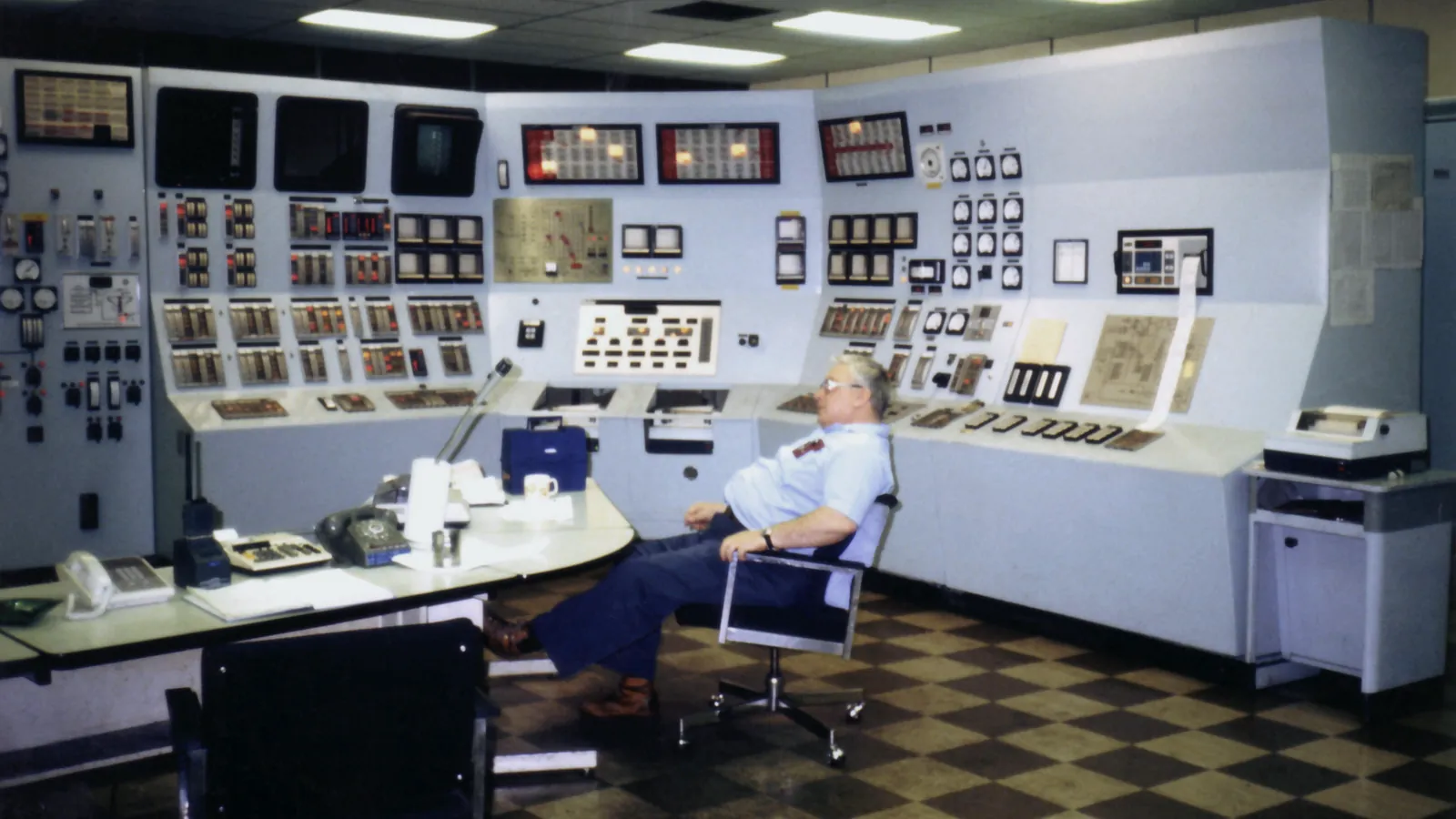
Terminal automation system (TAS) architecture consists of four layers: field devices (meters, valves, tank gauges, sensors), controllers (batch controllers, PLCs), terminal applications (TAS, TMS, gate) and enterprise systems (ERP, reporting), each needing its own interfaces and failure plan.
Drawing those layers is easy. Deciding which layer owns which decision, and what happens when the link between two layers breaks, is the real design work. The INTEGRA TAS product page shows one implementation of this chain, and the article on TAS, TMS and TPS explains how the application layer is divided.
Overview
The four layers and how they connect
Data moves up from the field and commands move down from the applications. Each arrow in the diagram is an interface that needs a protocol, an owner and a rule for what happens when it stops.
At the bottom, meters send pulses to batch controllers and tank gauges send levels to a gateway, often over Modbus. Controllers talk to the TAS over serial or Ethernet links. The TAS and TMS exchange orders, results and stock with the ERP over an application interface. Every protocol change is a translation point, and translation points are where data is lost or misread.
Measures loaded volume at each arm.
Hover, focus or tap a step to read its note.Reference model
Where a TAS sits in the ISA-95 model
ISA-95, also published as IEC 62264, is the common reference for splitting plant systems into levels. It describes five levels from the physical process (Level 0) to business planning and logistics (Level 4), and deals mainly with the interface between Levels 3 and 4.
A TAS fits Level 3, the operations layer, together with SCADA and the TMS. Batch controllers and PLCs sit at Level 2, sensors and valves at Level 1, and the ERP at Level 4. Using the same numbers in your drawings helps when IT and OT teams discuss who owns which server and which network.
- Level 4
- Business planning and logistics: ERP
- Level 3
- Operations management: TAS, TMS, SCADA
- Level 2
- Monitoring and supervisory control: PLC, batch controller
- Level 1
- Sensing and manipulating: meters, valves, sensors
- Level 0
- Physical process: tanks, pumps, product
Failure modes
What fails at each layer, and what keeps running
Each layer fails differently, so each needs its own answer to the question of what keeps running. The table gives the usual pattern.
| Criterion | Typical failure | What should keep running | Design answer |
|---|---|---|---|
| Field | Meter drift, sensor fault, loose pulse cable | Other bays and tanks | Diagnostics in the controller, spare devices |
| Control | Controller or PLC fault, power loss | Safe stop at the affected bay | UPS, fail-safe outputs, tested backups |
| Application | Server or network down | Running batches finish or stop safely | Standby server, local buffering, restore drill |
| Enterprise | ERP link down | Loading against received orders | Queued postings with retry and reconciliation |
Availability
Redundancy: where it pays and where it does not
Redundancy is worth paying for where one failure stops the whole terminal, and rarely elsewhere. A single bay controller failing stops one bay; a single TAS server failing can stop all of them.
That is why the TAS server, its database and the core network switch are the usual candidates for a standby. Power is the other common single point: a PLC panel without a UPS turns a short outage into a restart of every bay. Citia's UPS installation for PLC panels at the Donggala depot added UPS and automatic transfer switch units so the safety and process control panels stay powered while supply moves between the PLN grid and the generator.
Redundancy only helps if switchover is tested; an untested standby server often fails on the day it is needed.
Security
Network segmentation and IEC 62443
The boundaries between layers are the natural places to control traffic. A firewall between the application layer and the enterprise network stops an office problem from reaching the filling shed.
IEC 62443-3-3:2013 sets system security requirements for industrial control systems, tied to seven foundational requirements, and defines security levels a system can reach. The wider ISA/IEC 62443 series assigns shared responsibility to asset owners, product suppliers, integrators and service providers. In practice, a terminal starts with a few steps that need little new hardware.
Draw the zones
Mark which devices belong to field, control, application and enterprise networks.
Place the firewall
Put it between the application layer and the office or ERP network.
Use an exchange zone
Let the ERP and TAS meet on a server in between, not directly.
Control remote access
One controlled entry point, named accounts, sessions logged.
Keep restorable backups
Back up PLC, SCADA and TAS, and test a restore.
Deployment
On-premise, edge or cloud
A TAS can run fully on site, or split between edge equipment on site and a cloud service. The deciding question is what the terminal must still do when the internet link is down.
Citia's INTEGRA CTP, still in development, takes the split approach: gateways and edge software at each site collect data and keep local work going, the cloud layer handles workflows, inventory and documents, and PLC control and safety permissives stay in the local control system. How each site runs when the connection drops is assessed per implementation, which is the right question to ask of any cloud design.
| Criterion | On-premise TAS | Edge + cloud |
|---|---|---|
| Where the application runs | Servers at the terminal | Edge at site, workflows in the cloud |
| Internet outage | No effect on loading | Edge must carry local work until the link returns |
| Multi-site view | Needs a separate reporting layer | Built in |
| Site IT effort | Servers, backups and patching at each site | Smaller footprint, more network dependence |
Citia's micro webinar on reliable terminals uses the same layered view to diagnose faults, and the PLC/SCADA assessment article explains how to separate equipment, communication and application problems before deciding on replacement. At Pulau Layang, the support scope spans the SCADA system, electrical systems and safety equipment such as motor-operated valves and emergency shutdown valves, which is a reminder that the layers are maintained together.
Terms used in this article
- ISA-95 / IEC 62264
- Standard model that splits plant systems into Levels 0 to 4 and defines the business-to-operations interface.
- Layer
- A group of systems with the same role, such as control or application.
- Gateway
- Device that reads field protocols and passes normalised data upward.
- Standby server
- A second server that takes over when the main one fails.
- Network segmentation
- Splitting a network into zones with controlled traffic between them.
- Edge
- Computing equipment at the site that keeps local work running and syncs with the cloud.
- Security level
- In IEC 62443, a measure of how strongly a system resists attack.
Frequently asked questions
Does a TAS server need redundancy?
Yes, in most terminals the TAS server should have a tested standby, because its failure can stop every bay at once. Bay controllers usually do not need duplicates, since a single fault stops only one bay.
What keeps running when the connection to the ERP is lost?
Loading against orders already received should keep running when the ERP connection is lost. The TAS queues the results and posts them when the link returns, with a reconciliation report.
Where should the firewall be placed in a terminal network?
The main firewall belongs between the application layer and the enterprise or office network. Many terminals add an exchange zone in between so the ERP and TAS never connect directly.
When does a cloud-based TAS make sense?
A cloud-based TAS makes sense when several sites need one view and the design keeps control and safety local. The edge at each site must be able to carry local work through an internet outage.
Which protocols connect the layers of a TAS?
The layers of a TAS are usually connected by pulses and discrete signals at the bay, Modbus or vendor protocols to controllers and gauges, and application interfaces to the ERP. Each change of protocol needs a tested translation point.
Sources and further reading
- ISA-95 Standard: Enterprise-Control System Integration (opens in a new tab)
- IEC 62443-3-3:2013 System security requirements and security levels (opens in a new tab)
- ISA/IEC 62443 Series of Standards (opens in a new tab)
- INTEGRA CTP (Connected Terminal Platform) (opens in a new tab)
- Reliable terminals: TAS and control system reliability (opens in a new tab)
- LTSA for LPG Panjang (opens in a new tab)
- Cover photo by Achim Hering, public domain (opens in a new tab)
Next step
Prepare the technical discussion for your facility.
Bring the equipment list, diagrams and symptoms you have. The Citia team helps map the next step.
Related products and solutions
- KnowledgeTerminal Automation System (TAS): what it is, its components and how it worksA terminal automation system (TAS) runs fuel and LPG truck loading, from order and gate-in to metering, delivery documents and gate-out.
- KnowledgeWhat is SCADA? Components, architecture and industrial examplesSCADA collects data from PLCs, RTUs and instruments, shows it to operators and sends supervisory commands. Components, architecture and real plant examples.
- KnowledgeIntegrating TAS and TMS with SAP: what data flows and how to handle failuresA TAS and TMS link to SAP carries orders, filling results and tank stock. See the data per transaction and how queues, retries and reconciliation keep it correct when the connection fails.
- ProductINTEGRA CTPTerminal automation run from the cloud, with gateways and edge software at each site.
- ProductINTEGRA TASRuns truck loading at fuel and LPG terminals, from order and gate-in to filling and gate-out documents.
- KnowledgeTAS, TMS and TPS Integration: what does each system manage?Separate distribution processes, inventory measurements and document reporting before defining integration.
- KnowledgePLC/SCADA assessment: start with symptoms, topology and backupsSeparate equipment, communications, applications and operating processes before deciding on replacement.
- WebinarReliable terminals: TAS and control system reliabilityCitia Micro Webinar material examines terminal operations, field devices, controls, applications and fault diagnosis.
- ProjectPulau Layang distribution automationTAS operations and terminal-system support