
Process Safety
ESD vs SIS vs interlock, and what SIL means
Emergency shutdown (ESD) brings a process to a safe state; built to IEC 61511 with a target SIL, it becomes part of a safety instrumented system (SIS).
- Topic
- Process Safety
- Updated
- 13 November 2026
- Reading time
- 10 min
- Sections
- 8
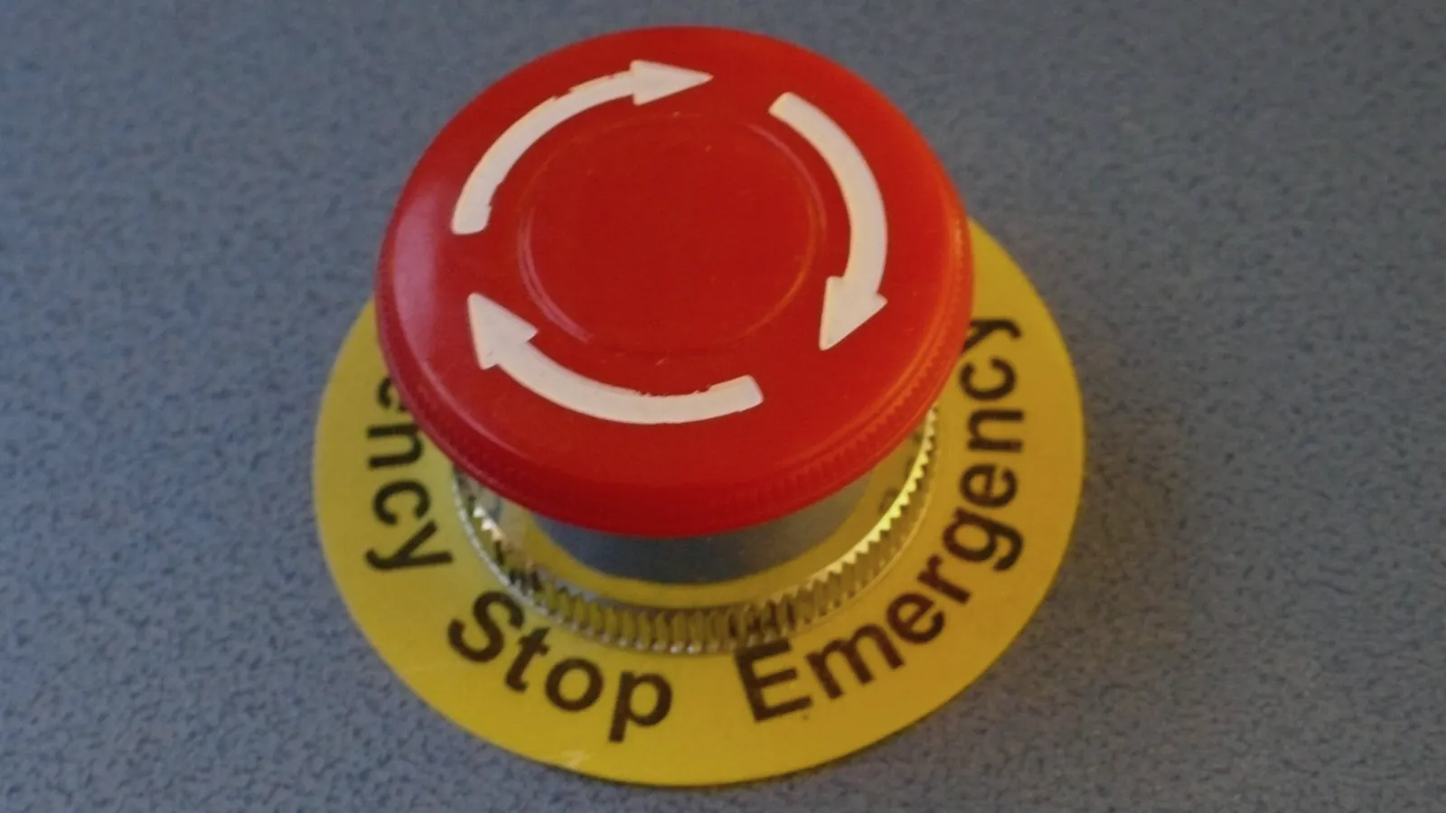
Emergency shutdown (ESD) is a function that brings a process to a safe state when a hazard appears. When that function is designed, verified and tested to IEC 61511 for a target safety integrity level (SIL), it becomes part of a safety instrumented system (SIS). An interlock is the wider idea: any logic that permits or blocks an action, such as a pump that cannot start against a closed valve.
The three terms overlap, and people use them loosely on site. This guide separates them, shows where each sits among the layers of protection, explains what SIL 1 to SIL 4 mean and says who decides the target. The examples come from fuel terminals, booster pump stations and marine loading arms.
Definitions
Three terms, one shutdown
ESD, SIS and interlock are three answers to one question, namely what stops the plant when something goes wrong. They differ in what they are, how they are built and how much proof they need.
An interlock is a rule in the control logic. "Start pump P-101 only if the suction valve is open" is an interlock. Interlocks usually live in the basic process control system (BPCS), a PLC or DCS, and most of them protect equipment or the sequence rather than people.
An ESD function takes the process to its safe state: stop the pumps, close the isolation valves, de-energise the loading arm. It can start from a sensor, from a fire and gas system or from a push button. On older terminals the ESD is often relay logic or a dedicated PLC wired to the shutdown valves.
A SIS is the set of sensors, logic solver and final elements that carries out one or more safety instrumented functions (SIF), each with a SIL target. IEC 61511 describes how to specify, design, test and maintain it. An ESD function that follows that standard is a SIF, and the hardware that runs it belongs to the SIS.
The BPCS is the normal control system. It keeps the process inside its limits day to day. IEC 61511 asks that the SIS be independent of it, so a single fault cannot remove both control and protection.
| Criterion | Interlock | ESD function | SIS function (SIF) | BPCS |
|---|---|---|---|---|
| What it is | Logic that permits or blocks an action | Action that takes the process to a safe state | Safety function built to IEC 61511 with a SIL target | Normal control and monitoring |
| Purpose | Protect equipment and keep the sequence correct | Stop flow and isolate when a hazard is detected | Lower the risk of a hazardous event by a stated factor | Keep the process inside its operating limits |
| Terminal example | Pump start blocked while the suction valve is closed | Booster pump trips and line valves close on high-high discharge pressure | The same trip, with a SIL target and proof tests | Pressure loop and the high-pressure alarm for the operator |
| Evidence needed | Function test at commissioning | Cause and effect matrix and function test | SIL verification, proof test interval, lifecycle records | FAT and SAT |
| Relation to the BPCS | Usually sits inside it | Preferably separate from it | Separate, as IEC 61511 expects | The control layer itself |
Two practical readings follow. First, every SIS function is a kind of interlock, but not every interlock is a SIS function. Second, "ESD" says what the function does, while "SIS" and "SIL" say how much evidence stands behind it.
A terminal can therefore have an ESD that works well and still has no SIL target on paper. That is a documentation gap, not proof of danger. The later sections show how it gets closed.
Layers
Where ESD sits among the layers of protection
A plant is never protected by one device. It is protected by layers, and each layer lowers the chance that a small upset grows into an accident.
The Center for Chemical Process Safety (CCPS) describes this in its layer of protection analysis (LOPA) method, and IEC 61511 draws the same picture. The SIS is the last layer that acts automatically. Layers beyond it either work without any signal, such as a relief valve or a bund wall, or depend on people.
Process design
Pipe ratings, pump curves and tank sizing set what can happen at all.
BPCS
The PLC or DCS holds pressure, flow and level inside operating limits.
Alarms and operator action
A high-pressure alarm tells the operator to act within a defined time.
SIS and ESD
Independent sensors and logic stop the pumps and close the valves automatically.
Physical protection
Relief valves, rupture discs and bund walls limit the release if shutdown fails.
Emergency response
Fire teams, site plans and, beyond the fence, community response.
LOPA gives each layer a credit, but only if the layer is independent, specific to the hazard, dependable and auditable. That is why the SIS cannot share a transmitter with the control loop that failed. If one pressure transmitter feeds both the PLC loop and the trip, a single stuck signal defeats two layers at once.
An alarm layer earns credit only when the operator has enough time to act and a clear response written down. If the time between the alarm and the hazard is too short for a person, the protection has to be automatic, and that is the case for a SIS.
The target SIL is simply the credit the SIS has to supply to bring the risk down to what the owner accepts.
Anatomy
How an ESD function works at a pump station
Every safety instrumented function has three parts: something that senses, something that decides and something that acts. The ESD at a booster pump is no different.
The sensor is a pressure transmitter, a gas detector, a level switch or a manual push button. The logic solver reads the sensor, compares it with a trip setpoint and drives its outputs. For a SIL-rated function this is usually a safety PLC certified to IEC 61508; on older plants it can be relay logic. The final elements are the pump starter and the emergency shutdown valve (ESDV), a valve that moves to a defined position when its signal is removed.
Design rules follow from how things fail. The function is normally energised, so a lost supply, a cut cable or a failed card drives the outputs to the safe state. Valves close by spring or stored air. Where a false trip is costly, designers vote the sensors, for instance two out of three, so one faulty transmitter neither blocks a trip nor causes one alone. Reset needs a deliberate operator action after the cause is cleared, so the plant cannot restart by itself.
Pressure transmitters, gas detectors and manual buttons. Voted when a false trip is costly.
Hover, focus or tap a step to read its note.The Citia project at Pertamina Pulau Baai, Bengkulu, shows the practical side. Citia worked on the pump emergency shutdown with PLC, relay and safety scope. The existing wiring diagrams, loop drawings and cause and effect did not fully match the field, so the team verified every signal point to point and updated the documents to the as-built condition. The new logic was simulated and tested offline, then connected during a scheduled shutdown.
One detail is typical. The fault indicator stayed active after a normal pump stop, because the fault status came from the existing variable speed drive. Integration problems like this show up only when someone tests against the real equipment.
The Citia bulletin on ESD for booster pumps on transmission pipelines lists the same needs: redundancy, accurate sensors, fast response, regular maintenance and a link to PLC and SCADA. The practical lesson is the same: list every trigger and every effect, then test end to end.
Integrity
What SIL 1 to SIL 4 mean
A safety integrity level is a number from 1 to 4 that states how reliable a safety function must be. The higher the number, the lower the allowed chance that the function fails when it is needed.
IEC 61508 defines the levels and IEC 61511 applies them to process plants. For a function that is called on rarely, called low demand mode, the measure is the average probability of failure on demand (PFDavg). IEC 61508-1 gives the bands in the table. A SIL 2 function, for example, has a PFDavg from 0.001 up to below 0.01.
| Criterion | PFDavg, low demand mode | Risk reduction factor |
|---|---|---|
| SIL 1 | 0.01 to below 0.1 | Above 10, up to 100 |
| SIL 2 | 0.001 to below 0.01 | Above 100, up to 1,000 |
| SIL 3 | 0.0001 to below 0.001 | Above 1,000, up to 10,000 |
| SIL 4 | 0.00001 to below 0.0001 | Above 10,000, up to 100,000 |
SIL belongs to a function, not to a device. A transmitter may be "suitable for SIL 2", which only says the manufacturer assessed it to IEC 61508. Whether the complete function, sensor plus logic solver plus valve, reaches SIL 2 depends on the architecture, failure rates, diagnostics, the proof test interval and the quality of the lifecycle process. The designer calculates and documents it. At a terminal the SIL number is rarely a goal in itself. It works as a shared language between owner, designer and maintenance team.
At a terminal the weakest element is usually the final element. A shutdown valve has moving parts and often sits idle until the day it is needed, so its proof test matters more than the logic card's datasheet.
IEC 61511 deals with SIL 1 to SIL 3, and SIL 4 is not considered in it. When a function seems to need SIL 3, it is common to ask first whether another layer or a design change can lower the demand.
Responsibility
Who sets the target SIL
The owner or operator of the facility decides, not the instrument vendor and not the installer. The target comes from a risk assessment of the hazard the function guards against.
The usual route has three steps. A hazard study such as HAZOP lists the scenarios, for example high pressure on a transfer pipeline. The team then estimates how often each scenario could happen and how severe it would be, using LOPA or a risk graph. Finally they compare the result with the risk the owner accepts. The gap is the risk reduction the SIF must supply, and that sets the SIL.
Designers and integrators then verify the achieved SIL against the target, and the owner keeps the evidence for audits. IEC 61511 organises all of this as a safety lifecycle with a safety requirements specification (SRS) at the centre.
The safety lifecycle in six phases
- Phase 1
Hazard and risk assessment
HAZOP and LOPA identify scenarios and the risk to cover.
- Phase 2
Allocation and target SIL
Each safety function is assigned a layer and a SIL.
- Phase 3
Safety requirements specification
Trip points, response times, safe states and reset rules in writing.
- Phase 4
Design, verification, FAT
The achieved SIL is calculated, then tested in the factory.
- Phase 5
Installation and validation
Point-to-point checks and a full-function test on site.
- Phase 6
Operation and change control
Proof tests, bypass records and a review of every modification.
Many ESD systems on terminals were built before the owner set SIL targets. IEC 61511 expects owners to assess existing systems too, and to show they are designed, maintained, tested and operated safely. The practical start is the one used at Pulau Baai: rebuild the cause and effect matrix and the drawings from the field, then decide which functions deserve a SIL target.
Pitfalls
Mix-ups that cause arguments on site
Four mix-ups come up again and again in design reviews, mostly because the words are used loosely in daily talk.
- "ESD" means the red button. The button is only one trigger. The ESD function is the whole chain from every trigger to every final element.
- "SIL-rated valve" means the loop is SIL-rated. The label describes the valve's suitability. The loop reaches a SIL only after sensor, logic solver and valve are calculated together.
- "Redundant" means safe. Two transmitters on the same impulse line, or powered from the same supply, can fail together. Redundancy helps when failures are independent, or when the design accounts for the common cause.
- "Process shutdown" and "emergency shutdown" are the same. Many plants separate them. A process shutdown stops a unit after an operating upset, while an emergency shutdown answers a hazard and may isolate a whole area. The levels and their names come from the owner's shutdown philosophy, so ask for that document before you read a cause and effect matrix.
Operation
Keeping an ESD working after commissioning
A shutdown function earns its SIL on paper and keeps it, or loses it, in operation. Four habits decide which.
Proof tests. A dangerous failure in a trip function stays hidden until the next demand, and a proof test finds it. The interval, the steps and the pass criteria come from the safety requirements specification. Test from the sensor to the final element, including the valve stroke time and the status feedback in SCADA.
A partial stroke test moves the valve part of the way between full tests. It adds diagnostic coverage but does not replace the full-stroke test, which many terminals schedule during planned shutdowns because stroking a line valve interrupts product movement.
Bypass control. Operators sometimes inhibit a trip during start-up or while a transmitter is faulty. Every bypass needs written authorisation, a time limit, a compensating measure such as an operator on watch, and a visible indication in the control room. A bypass that nobody remembers is one way a function loses its integrity without any equipment failing.
Change control. Changing a trip setpoint, replacing a transmitter with another model or moving a signal to a different card is a modification. IEC 61511 asks for a review before the change and a re-test after it.
Spurious trips. Each unwanted shutdown interrupts product movement and stresses pumps and valves. Operators who live with repeated false trips start to distrust the system and bypass it. That is the reason for sensor voting and for diagnostics that tell a faulty transmitter from a real process event.
- Function and reference
- Tag of the function and the SRS revision it was tested against.
- Who, when, which procedure
- Tester names, date, test procedure and its revision.
- Sensor check
- Method used: simulated signal or real process change, and the trip value seen.
- Final element
- Valve stroke time and end position, pump stop confirmed.
- Alarms and SCADA
- First-out cause, alarm text and valve status as shown to the operator.
- Deviations
- Repairs, re-tests and every bypass used during the test.
Practice
Where terminals use ESD and interlocks
No rule says every pump needs a SIL-rated ESD. The hazard study decides, based on what a failure could release, where, and which other layers exist. What a terminal almost always has is a small set of shutdown triggers.
- High pressure or loss of containment on a transfer pipeline or booster pump discharge.
- Gas or fire detection in a pump area or loading bay, covered in fire and gas systems.
- High-high tank level, the overfill case.
- Arm excursion or vessel movement at a marine loading arm.
- Manual push buttons in the control room and in the field.
Cause               P101 XV201 Horn
PT201 HH (2oo3)      X     X     X
GD301 gas high       X     X     X
PB01 pressed         X     X     X
Fire alarm, pump     X     X     X
ESD power lost X X -Each row is a cause, each column an effect. Review it with operations before the first test.
Interlocks at the loading bay do the everyday work: no preset until the grounding is verified, no flow unless the overfill probe reads dry, no gate release until the transaction closes. They live in the batch controller and PLC, described in the batch controller guide and the filling shed guide, and the grounding permissive is covered in static grounding during loading.
The Citia work at Pertamina Priok adds a pipeline example. Pressure transmitters, temperature transmitters and gas detectors feed the control system, and an out-of-range value raises an alarm and sends a trip to the shutdown valve. The unloading and backloading restoration covers HMI, PLC, panels and sensors for that protection.
Terms used in this article
- ESD (emergency shutdown)
- A function that stops equipment and isolates the process when a hazard appears.
- ESDV
- Emergency shutdown valve. It moves to a defined safe position when its signal or power is lost.
- Interlock
- Logic that permits or blocks an action depending on conditions.
- BPCS
- Basic process control system: the PLC or DCS that runs the process day to day.
- SIS
- Safety instrumented system: sensors, logic solver and final elements that perform safety functions.
- SIF
- Safety instrumented function: one protective action with its own SIL target.
- SIL
- Safety integrity level, 1 to 4: how reliable a safety function must be.
- PFDavg
- Average probability of failure on demand, the measure used for low demand functions.
- LOPA
- Layer of protection analysis: a method that credits each protection layer to find the risk left.
- Proof test
- A periodic test that finds hidden dangerous failures in a safety function.
Frequently asked questions
What is the difference between an ESD and an ordinary interlock?
An ESD takes the whole process or a section to its safe state when a hazard appears, while an ordinary interlock only permits or blocks one action. A pump-start interlock protects the pump; an ESD stops the line because pressure or gas reached a hazardous level. Both can be written in the same PLC, but only the ESD carries a safety duty.
What does SIL mean?
SIL, safety integrity level, is a number from 1 to 4 that states how reliable a safety function must be. Each step up cuts the allowed average probability of failure on demand by a factor of ten. The level applies to the whole function, so it is calculated for sensor, logic solver and final element together.
Is an ESD system the same as a SIS?
No. ESD describes what a function does, a SIS describes how it is built and proven. An ESD becomes part of a SIS when it is specified, designed, verified and tested to IEC 61511 for a target SIL. An ESD built before that, or without a SIL target, still works, but it lacks that evidence.
Does every fuel pump need an ESD?
Not automatically; the hazard study decides. A pump whose failure could release flammable product in quantity, or overpressure a line, usually earns a shutdown function, while a small transfer pump with other protection may need only an interlock. The decision and its reasons belong in the safety documentation.
Who decides the target SIL?
The facility owner or operator decides, based on a risk assessment such as HAZOP followed by LOPA or a risk graph. The vendor supplies certified components and failure data, and the integrator verifies the built function against the target. Nobody else can accept the risk on the owner's behalf.
Can a normal PLC be used as the ESD logic solver?
For a function with a SIL target, the logic solver must be suitable for that SIL, usually a safety PLC certified to IEC 61508. A general-purpose PLC may be used only where the SIS designer can justify it for the target and keeps it independent of the control system. Relay logic remains common on older terminals.
How often must an ESD be tested?
The interval comes from the SIL verification and the owner's procedure, so there is no single number. A shorter interval lowers the PFDavg of the function, which is why the proof test interval is written into the safety requirements specification. Record every test, including the valve closing time.
Sources and further reading
- IEC 61511-1:2016 Functional safety, safety instrumented systems for the process industry sector, Part 1 (opens in a new tab)
- IEC 61508-1:2010 Functional safety of electrical, electronic and programmable electronic safety-related systems, Part 1 (opens in a new tab)
- Layer of Protection Analysis: Simplified Process Risk Assessment (opens in a new tab)
- Pump emergency shutdown (ESD) at Pertamina Pulau Baai (opens in a new tab)
- ESD systems for fuel pipeline operations (opens in a new tab)
- Cover photo by Tim Regan from Cambridge, UK, CC BY 2.0 (cropped and colour graded) (opens in a new tab)
Next step
Prepare the technical discussion for your facility.
Bring the equipment list, diagrams and symptoms you have. The Citia team helps map the next step.
Related products and solutions
- KnowledgeHigh and high-high tank level alarms: overfill protection under API 2350A high alarm warns that a tank is nearing its normal fill limit; the high-high alarm is the last layer before the critical level and should come from a sensor independent of the ATG.
- KnowledgeFire and gas systems and early warning at fuel terminalsA fire and gas system detects fire and flammable gas, sounds alarms and trips the process; this guide covers detectors, logic, early warning and PAGA at fuel terminals.
- KnowledgeHazardous areas and explosion-proof equipment: zones and Ex certificationHazardous areas are split into Zone 0, 1 and 2 by how often an explosive atmosphere appears; electrical equipment in them needs an Ex certificate that matches the zone.
- ProjectPertamina Pulau Baai: pump emergency shutdown (ESD)The Pump Emergency Shutdown (ESD) project improves the safety and reliability of pump operation by adding automatic and manual shutdown functions for emergencies.
- NewsESD systems for fuel pipeline operationsCovers booster pump Emergency Shutdown on fuel transmission pipelines, including high-pressure response and monitoring integration.
- NewsMarine loading arm (MLA) integration with SCADA for terminal operationsCovers Marine Loading Arm automation with SCADA monitoring, automatic control and Emergency Shutdown integration during unloading.
- ProjectPertamina Priok: unloading and backloading system restorationPressure, temperature and gas monitoring at the Pertamina Priok port trips the shutdown valve when a limit is exceeded during unloading and backloading.
- ProjectBalongan PressMon communication restorationPressMon communications-network and panel maintenance
- KnowledgePLC/SCADA assessment: start with symptoms, topology and backupsSeparate equipment, communications, applications and operating processes before deciding on replacement.