
Industrial protocols
Troubleshooting Modbus RS-485 communication
Most Modbus RS-485 faults start at the physical layer. A field checklist for termination, biasing, topology, grounding, serial settings and exception codes.
- Topic
- Industrial protocols
- Updated
- 13 November 2026
- Reading time
- 6 min
- Sections
- 7
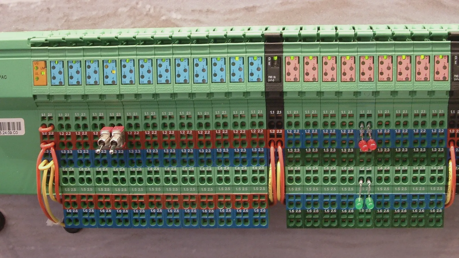
Most Modbus RS-485 faults come from the physical layer: wrong termination and biasing, a star topology, unequal ground, or baud rate and parity settings that differ between devices. Software and register maps cause fewer outages than cables, connectors and converters.
Modbus RTU runs on RS-485 as a request/reply protocol: a master polls each slave by address, and each frame ends with a CRC. When a value freezes on the HMI, the fault can sit in any layer between the sensor and the screen. Work from the bottom up. Check the cable and the line design first, then the serial settings, then the Modbus replies.
Method
Start at the physical layer
Troubleshooting RS-485 is faster when you test one layer at a time and write down what each test proves.
Begin with the symptom and its pattern. A device that never answers points to wiring, address or settings. A device that answers sometimes points to noise, reflections, a missing bias or a timeout set too short. Errors that grow when a pump or a VSD starts point to grounding and shielding.
Measure before you change anything. With the line idle, a healthy biased pair sits at a steady differential voltage, and an unbiased pair floats. Then power the line down and put a multimeter across the pair. Two terminations in parallel read about half of one resistor; a reading near one resistor means the second end is missing.
When the line carries many devices, split it. Disconnect the far half of the trunk, terminate the new end, and test again. If the near half becomes stable, the fault sits in the part you removed. Repeat until one segment or one device remains. This halving method finds a damaged junction box or a device that loads the line faster than checking every terminal in order.
Record the symptom
Which devices fail, how often, at what time, and what else was running.
Check the cable and topology
Daisy chain, short stubs, polarity of the pair, common wire present, shield intact.
Check termination and bias
Two terminations at the trunk ends, one bias pair for the whole line.
Check serial settings
Same baud rate, parity and stop bits on every device; unique addresses.
Test one device alone
Read a known register from a laptop master with only that device connected.
Read the replies
Silence, CRC errors and exception codes each point to a different layer.
Topology
Wire RS-485 as a daisy chain, not a star
RS-485 is designed as one long cable that visits each device in turn, not as a hub with branches.
The Modbus over Serial Line specification V1.02 describes one trunk cable with a line termination at each end. Devices connect directly on the trunk or through short derivation cables, never longer than 20 m. A star, where several long cables leave one junction box, creates several open ends that reflect the signal back into the line.
The Texas Instruments RS-485 Design Guide gives the same advice: a daisy chain with short stubs. Reflections rarely kill a line outright. They corrupt some frames, so the symptom is a device that drops out now and then.
| Criterion | Daisy chain | Star |
|---|---|---|
| Cable path | One trunk from device to device | Several long branches from one box |
| Line ends | Two, both terminated | One per branch, cannot all be terminated |
| Stubs | Short, 20 m or less | Long branches act as stubs |
| Typical symptom | Stable when settings are right | Random CRC errors and dropouts |
Line design
Termination and biasing: two resistors, one pair
A termination resistor stops the signal bouncing back at the cable end, and a bias pair holds the idle line in a known state.
The serial specification requires a line termination near each end of the bus and allows no more than two on one pair. It suggests a 150 ohm resistor, or 120 ohm in series with a 1 nF capacitor when the line is biased. Never put a termination on a derivation cable.
Biasing, which the specification calls line polarization, uses a pull-up to 5 V on D1 and a pull-down to common on D0, both between 450 and 650 ohm. Fit one pair for the whole line, usually at the master. Many devices have termination and bias switches built in, and three or four of them switched on together load the line until the master can no longer drive it.
- Termination value
- 150 ohm (0.5 W), or 120 ohm (0.25 W) + 1 nF in series when biased
- Number of terminations
- Two per pair, one near each trunk end
- Bias resistors
- 450-650 ohm, pull-up on D1, pull-down on D0
- Bias location
- One point for the whole line, usually the master
- Devices without repeater
- 32 always allowed; 4 fewer when the line is biased
- Trunk length
- Up to 1000 m at 9600 baud, AWG26 or wider
Grounding
Common, shield and surge protection
RS-485 needs a third wire, the common, because two devices far apart rarely sit at the same ground potential.
The serial specification requires a common conductor linking all devices, connected to protective ground at one point only, usually at the master. The cable must be shielded, with the shield grounded at one end. The RS-485 Design Guide warns that ground potential differences between distant nodes add common-mode noise. Receivers tolerate a common-mode range of -7 V to +12 V; beyond that, frames fail or transceivers are damaged.
Outdoor lines in tank farms also need surge protection. Lightning induction and switching of large loads push transients into long cables. Isolated transceivers or isolated gateways help where ground potentials differ a lot, for example between a jetty panel and the control room.
The MOV communication path at Fuel Terminal Jambi shows the pattern. A surge protection device sits on the RS-485 line before the Advantech ECU-1051 gateway. A LAN arrester protects the Ethernet side toward InduSoft SCADA.
Common wire to every device
Grounded at one point, usually the master.
Shield grounded at one end
Connector shells bonded to the shield.
Surge protection on long runs
On the RS-485 side and the Ethernet side.
Settings
Serial settings that must match on every device
One device with a different baud rate or parity can make a whole line look broken, because its garbled replies collide with good frames.
The serial specification requires 9600 and 19200 baud, with 19200 as the default, and even parity as the default format. No parity is allowed but then needs 2 stop bits. Addresses run from 1 to 247 and must be unique on the line. Two devices sharing one address answer together and corrupt each other.
Timing matters as much as the settings. The master needs a response timeout long enough for the slowest device, and the specification gives one to several seconds at 9600 baud as typical. A timeout that is too short shows up as intermittent failures on the slowest device only.
Keep one line sheet per serial line, like the example below, and update it with every change. It turns a two-hour search into a five-minute comparison.
RS-485 line sheet: one page per serial line (example layout)

Line          : TK-FARM-A, gateway port 1
Master        : gateway, Modbus RTU master
Settings      : 19200 baud, 8 data bits, even parity, 1 stop bit
Timeout       : 1000 ms per request, 2 retries
Termination   : at gateway (end 1) and at device 4 (end 2) only
Biasing       : one pair, at gateway only
Common / shield: common to protective ground at gateway; shield grounded at one end

Order on cable  Address  Device          Register block read
1               1        Tank gauge T-01  0-7 (FC 03)
2               2        Tank gauge T-02  0-7 (FC 03)
3               3        Tank gauge T-03  0-7 (FC 03)
4 4 Power meter per vendor map (FC 04)Diagnosis
What timeouts, CRC errors and exception codes mean
The reply from a device, or the lack of one, tells you which layer to look at next.
No reply at all means the request never arrived in a form the device accepted: wrong address, wrong baud rate or parity, swapped pair, broken cable or a dead device. CRC errors mean bytes arrived damaged, which points to noise, reflections or grounding. An exception reply is good news for the cable. It proves the frame crossed the line intact and the device answered on purpose.
A Modbus test program on a laptop acts as a temporary master and shows the raw bytes. Connect it close to one device, read one register from the vendor map, and compare. If the test works and the system master does not, the problem is in the master configuration or the path between them.
Watch the polling load as well. Each retry after a timeout holds the line for another full timeout, so one dead device can slow the update rate of every healthy device on the same line. Set a sensible retry count, and let the master mark a failed device as offline instead of hammering it on every cycle.
| Criterion | Meaning | Check first |
|---|---|---|
| No reply (timeout) | Request not accepted or reply lost | Address, baud, parity, pair polarity, cable |
| CRC error | Bytes damaged on the line | Termination, bias, grounding, stubs |
| Exception 01 | Function code not supported | FC 03 vs FC 04 in the vendor map |
| Exception 02 | Address does not exist | Offset by one, block past the last register |
| Exception 03 | Invalid value in the request | Quantity too large, malformed request |
| Exception 0B | Gateway target did not respond | Serial side of the gateway |
In the field
Field notes from Citia projects
In Citia projects, restoring a Modbus line has usually meant replacing a converter or gateway and then proving the path end to end.
At Jambi, the ATG gateway replacement started with a new Advantech ECU-1051 and a full gateway reconfiguration. The team then checked the RS-485 Modbus link from the ATGs and the Ethernet link to the TMS, and added surge protectors on both lines. The project record states that line protection should be installed from the start in areas prone to lightning.
At Cikampek, meter reading stopped until the Moxa NPort 5160 serial gateway was replaced and its serial and network parameters configured again. At ITJ LPG Priok, new pressure and temperature transmitters came online after the team checked the wiring thoroughly and adjusted the PLC and transmitter configuration.
The common thread is documentation. After every repair, the Citia team records the serial settings, addresses, termination points and the result of the end-to-end test. The next fault on the same line then starts from known facts instead of guesses, and the operations team can see exactly what changed.
Terms to know
- Termination resistor
- A resistor across the pair at each end of the trunk that absorbs the signal and stops reflections.
- Biasing (line polarization)
- A pull-up and pull-down pair that holds the idle line in a defined state so receivers do not read noise as data.
- Daisy chain
- Wiring where one cable runs from device to device in order, with two ends.
- Stub (derivation)
- A short branch cable from the trunk to one device; the serial specification limits it to 20 m.
- Common
- The third conductor of an RS-485 line that gives all devices a shared reference.
- Baud rate
- The speed of the serial line in bits per second; every device on one line must use the same value.
- Parity
- A check bit added to each character; even parity is the Modbus default.
- Response timeout
- How long the master waits for a reply before it counts the request as failed.
- Exception code
- A one-byte reason a device sends when it refuses a valid Modbus request.
Frequently asked questions
Why does my Modbus device answer sometimes but not always?
Intermittent Modbus replies usually come from reflections, a missing bias, ground noise or a timeout that is too short. Check the termination at both trunk ends, the bias pair, the common wire, and whether errors rise when large motors start.
Do I need a 120 ohm termination resistor on RS-485?
Yes, an RS-485 line needs a termination at each end of the trunk, and only there. The Modbus serial specification suggests 150 ohm, or 120 ohm in series with 1 nF when the line is biased. Short, slow lines may work without it, but they fail more easily.
How do I read a Modbus exception code?
Read a Modbus exception code by looking at the second and third bytes of the reply: the function code plus 0x80, then the code. 01 is an unsupported function, 02 a wrong address, 03 an invalid value, 04 a device failure.
What is Modbus Poll?
Modbus Poll is a Windows test program that acts as a Modbus master, so you can read and write registers from a laptop. Tools of this kind let you test one device without the SCADA system and see the raw frames.
What cable should I use for RS-485 Modbus?
Use a shielded cable with one twisted pair for data and a third wire for the common. The Modbus serial specification states AWG 24 is always sufficient for Modbus data, and a characteristic impedance above 100 ohm is preferred at 19200 baud and higher.
Can RS-485 devices be wired in a star?
No, RS-485 should not be wired as a star with long branches. Each branch adds an unterminated end that reflects the signal. Use a daisy chain, keep stubs to 20 m or less, or use an RS-485 hub or repeater that gives each branch its own terminated segment.
Sources and further reading
- MODBUS over Serial Line Specification and Implementation Guide V1.02 (opens in a new tab)
- MODBUS Application Protocol Specification V1.1b3 (opens in a new tab)
- The RS-485 Design Guide (SLLA272D) (opens in a new tab)
- NPort 5100 Series serial device servers (opens in a new tab)
- Jambi fuel terminal: replacement of ATG gateway (ECU) spare part (opens in a new tab)
- Motor-operated valve (MOV) communication (opens in a new tab)
- Cover photo by S.J. de Waard, CC BY 2.5 (cropped and colour graded) (opens in a new tab)
Next step
Prepare the technical discussion for your facility.
Bring the equipment list, diagrams and symptoms you have. The Citia team helps map the next step.
Related products and solutions
- KnowledgeWhat is Modbus? RTU vs TCP, registers and function codesModbus is an open protocol for industrial devices. This guide compares Modbus RTU and TCP and explains registers, function codes, frames and gateways.
- KnowledgePLC troubleshooting: safe steps from symptom to fixMake the process safe, save the running program, then check power, CPU, I/O, wiring, communication and logic in that order. Symptom table and field cases.
- Knowledge4-20 mA and HART: how field instruments send dataA 4-20 mA loop sends a measurement as current; HART adds digital data on the same wires. How the loop works, how to convert mA to a value, and how to read faults.
- ProjectJambi fuel terminal: replacement of ATG gateway (ECU) spare partThis project replaced the spare part Gateway ATG ECU-1051 Advantech at the Jambi fuel terminal to restore data communication between the Automatic Tank Gauging (ATG) and the Tank Management System (TMS) application.
- ProjectMotor-operated valve (MOV) communicationRestoration of Flowserve Limitorque MOV communication to InduSoft SCADA at Fuel Terminal Jambi, through RS-485, an SPD, an ECU-1051 gateway and a LAN arrester.
- ProjectSupply of Allen-Bradley PLC digital output modules and Moxa converterTroubleshooting and replacement of a faulty Allen-Bradley PLC digital output and a Moxa NPort 5160 meter reading gateway at the Cikampek fuel terminal.
- ProjectPertamina ITJ LPG Priok: transmitter replacement in areas PMB III and IVPressure and temperature transmitters installed and integrated with the PLC and HMI in areas PMB III and IV of the Pertamina ITJ LPG Priok terminal.
- ProductCATALYST TelemeteringBrings level, pressure and panel readings from remote sites to one dashboard.
- KnowledgePLC/SCADA assessment: start with symptoms, topology and backupsSeparate equipment, communications, applications and operating processes before deciding on replacement.