
Industrial protocols
What is Modbus? RTU vs TCP, registers and function codes
Modbus is an open protocol for industrial devices. This guide compares Modbus RTU and TCP and explains registers, function codes, frames and gateways.
- Topic
- Industrial protocols
- Updated
- 13 November 2026
- Reading time
- 10 min
- Sections
- 8
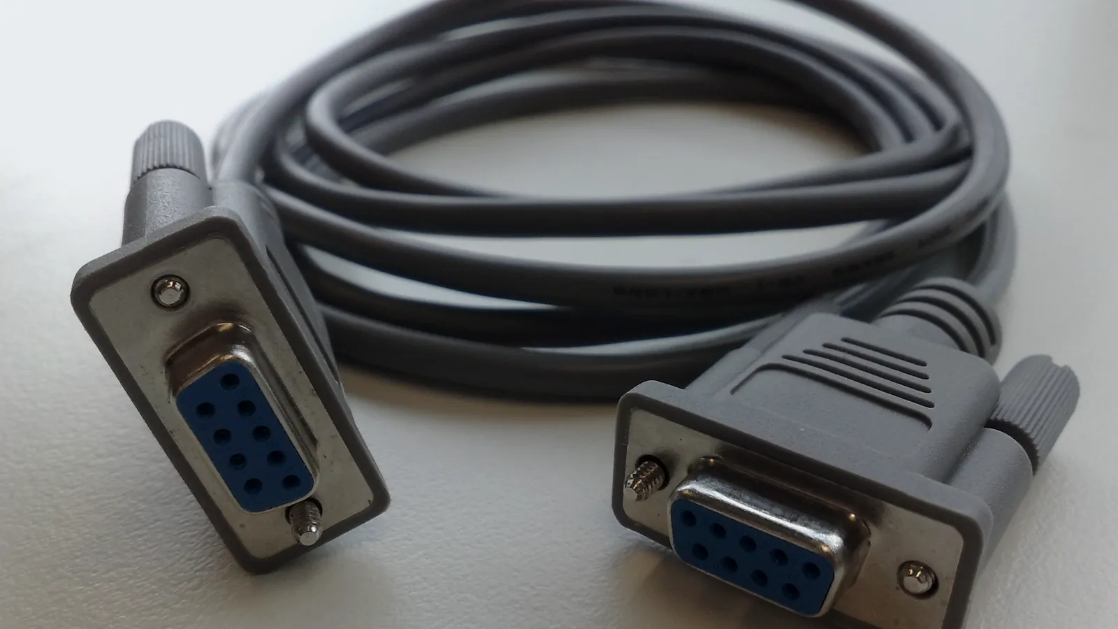
Modbus is an open communication protocol for industrial devices; Modbus RTU runs on serial lines such as RS-485 with a CRC check, while Modbus TCP runs on Ethernet TCP/IP on port 502. The Modbus Organization describes it as the serial de facto standard of the industry since 1979, in the Modbus Application Protocol Specification V1.1b3.
At a fuel terminal, Modbus carries readings from automatic tank gauges (ATG), flow meters, motor-operated valves (MOV) and power meters into PLC, SCADA and tank management software. Modbus moves numbers, not meaning. The register map published by each device maker says what every number is, in which unit and in which format.
Modbus stays common because it is simple to implement, the specifications are free to download, and almost every PLC, gateway and SCADA package can speak it. The price of that simplicity is that Modbus knows nothing about units, quality flags or security. Those gaps are filled by documentation, network design and, where needed, newer protocols such as OPC UA or MQTT on top.
For a terminal team, understanding Modbus means being able to read vendor documents, check gateway settings and tell a cable fault from a configuration error. That basic skill shortens fault finding when tank data or valve status suddenly freezes on the operator screen.
Basics
How Modbus works: one device asks, another answers
Modbus works like a roll call: one device asks a question and only the addressed device answers.
The specification places Modbus at the application layer (layer 7 of the OSI model) as a request/reply protocol. The device that asks is the client, called the master on a serial line. The device that answers is the server, called the slave on a serial line. A server never sends data on its own, which keeps the protocol small and the polling cycle predictable.
Each request carries a function code that says what to do, such as read registers or write a coil, and a data field that says where and how much. The server returns the data or an exception response. That response repeats the function code plus 0x80 and adds a one-byte exception code that explains the refusal.
In a typical terminal, a SCADA server or an industrial gateway is the client. It polls each device in turn: tank gauges, flow computers, valve actuators, power meters. Poll time grows with the number of devices and registers, so the polling list deserves the same design attention as the cabling.
On a serial line the client may also send a broadcast with address 0. Every server acts on it and none replies, so broadcasts suit writing commands only. After a broadcast the client waits a turnaround delay before the next request. The serial specification gives 100 to 200 ms as typical for that delay, and a response timeout of one to several seconds at 9600 baud for normal requests.
Modbus client. Polls each device and stores values as tags.
Hover, focus or tap a step to read its note.Comparison
Modbus RTU vs Modbus TCP: what changes
Modbus RTU and Modbus TCP carry the same requests; the difference is the cable underneath and the way each frame is wrapped.
Modbus RTU sends binary frames over a serial line, usually two-wire RS-485. A frame starts with the server address, then the function code, the data and a 16-bit CRC. The Modbus over Serial Line specification V1.02 sets addresses 1 to 247 for servers and reserves 0 for broadcast. Frames are separated by a silence of at least 3.5 character times, and the default format is 8 data bits with even parity.
Modbus TCP puts the same protocol data unit (PDU) inside a TCP/IP packet. The serial address and the CRC disappear. A 7-byte MBAP header takes their place, with a transaction identifier, a protocol identifier, a length field and a unit identifier. The Messaging on TCP/IP Implementation Guide reserves port 502, and IANA registers that port as mbap.
Choose by topology, not by habit. RS-485 suits a string of field devices spread over hundreds of metres on one pair of wires. Ethernet suits panels and servers that already share a network, and lets several clients read the same device if the device accepts more than one connection.
Every device on one RTU line must share the same baud rate, parity and stop bits. The serial specification requires 9600 and 19200 baud, with 19200 as the default, and requires 2 stop bits when no parity is used. A third serial form, Modbus ASCII, sends readable characters with an LRC check; it still exists on older equipment but is rare in new terminals.
| Criterion | Modbus RTU | Modbus TCP |
|---|---|---|
| Physical layer | Serial line, mostly 2-wire RS-485; RS-232 for point to point | Ethernet with TCP/IP |
| Roles | One master and up to 247 slaves per line | Clients and servers; several clients can poll one server |
| Addressing | Slave address in every frame | IP address plus unit identifier in the MBAP header |
| Error check | CRC-16 at the end of each frame | Handled by TCP; no Modbus CRC |
| Frame boundary | Silence of at least 3.5 character times | Length field in the MBAP header |
| Reach | Up to 1000 m at 9600 baud with AWG26 or wider cable (serial spec V1.02) | Set by the Ethernet segment; extend with switches or fibre |
Data model
Coils, discrete inputs and registers
Modbus stores data in four tables, and every value you read lives in one of them.
The Application Protocol Specification defines two single-bit tables and two 16-bit tables. Coils are read-write bits for commands such as open or stop. Discrete inputs are read-only bits, such as a limit switch or an alarm contact. Input registers are read-only words, usually measurements. Holding registers are read-write words for setpoints and configuration, and many devices put measurements there too.
Each table can hold up to 65,536 items, addressed from 0 to 65535 inside the frame. Values travel big-endian, high byte first. A value wider than 16 bits, such as a 32-bit float for tank level, spans two registers, and the device maker decides the word order.
The four tables may be separate memory areas or overlap inside the device; the specification allows both. In practice, many tank gauges and meters expose everything as holding registers, so a client often needs only function code 03 for reading and 06 or 16 for writing.
- Coils
- 1 bit, read-write (FC 01, 05, 15)
- Discrete inputs
- 1 bit, read-only (FC 02)
- Input registers
- 16-bit word, read-only (FC 04)
- Holding registers
- 16-bit word, read-write (FC 03, 06, 16)
- Items per table
- Up to 65,536 (addresses 0-65535)
- Byte order
- Big-endian inside each register
Register map
What a Modbus register map tells you
A register map is the dictionary of a device: it lists which address holds which value, in which format and unit.
Two conventions cause most first-day confusion. Many manuals write holding registers as 40001, 40002 and so on, a numbering inherited from Modicon controllers. The frame itself carries a zero-based address, so 40001 travels as 0. The example in the Application Protocol Specification reads registers 108 to 110 by sending a starting address of 107 (0x006B).
The second trap is the data type. A level sent as FLOAT32 needs both registers read in one request and decoded in the right word order. Read them in two requests and the halves may come from different scans. Integer registers often carry a scale factor that the client must apply before the value reaches the operator screen.
Ask the vendor for the map that matches the installed firmware, not the brand brochure. INTEGRA TMS reads ATGs from Honeywell, Endress+Hauser and Tokyo Keiso, and two gauges from the same maker can still expose different maps.
A usable register map settles four points before anyone opens a laptop on site:
- Addressing: zero-based or one-based, and the table each address belongs to.
- Data type: INT16, UINT16, INT32 or FLOAT32, and the word order of every 32-bit value.
- Unit and scale: the engineering unit, the scale factor, and the value that means "no reading" or "gauge fault".
- Write access: which registers may be written, and what the device does when they are.
Example register map: tank gauge on RS-485 (illustrative, not a real device)
Server address: 1   Baud: 9600   Format: 8 data bits, even parity, 1 stop bit

Manual ref  PDU addr  Words  Type     Unit    Value
40001       0         2      FLOAT32  mm      Product level
40003       2         2      FLOAT32  mm      Free water level
40005       4         2      FLOAT32  degC    Average product temperature
40007       6         1      UINT16   -       Status bits (0 = level OK, 1 = gauge fault)
40008       7         1      UINT16   -       Alarm bits (0 = H, 1 = HH, 2 = L, 3 = LL)

Notes
- FLOAT32 spans two registers. Word order: high word first (check the manual).
- Read 40001 to 40008 in one request: FC 03, start 0, quantity 8.Function codes
The Modbus function codes you will use most
A function code is the verb of a Modbus request: one byte that tells the server whether to read or write, and which table to use.
Eight public codes cover almost all field integration work. Other codes, such as serial diagnostics or file record access, are rarely needed for tanks, meters and valves. The Application Protocol Specification limits each read: up to 2000 coils or discrete inputs, and up to 125 registers with function codes 03 and 04. Function code 16 writes up to 123 registers in one frame.
When a device refuses a request, it answers with the function code plus 0x80. Exception 01 means the function is not supported and 02 means the address does not exist. Exception 03 means a value in the request is invalid, and 04 means the device failed while executing it. Gateways add 0A and 0B when the path or the device behind them does not answer.
Treat write codes with care on a live plant. Function codes 05, 06, 15 and 16 change outputs and setpoints immediately, with no confirmation step inside the protocol. Agree in the design which registers a client may write, test writes during a work window, and keep commands for valves and pumps behind the interlocks of the control system.
| Criterion | Name | Data table | Typical use |
|---|---|---|---|
| 01 (0x01) | Read Coils | Coils | Read pump run commands |
| 02 (0x02) | Read Discrete Inputs | Discrete inputs | Read limit switches and alarm contacts |
| 03 (0x03) | Read Holding Registers | Holding registers | Read tank level, setpoints, meter totals |
| 04 (0x04) | Read Input Registers | Input registers | Read measured values on many meters |
| 05 (0x05) | Write Single Coil | Coils | Send open, close or stop to a valve |
| 06 (0x06) | Write Single Register | Holding registers | Change one setpoint |
| 15 (0x0F) | Write Multiple Coils | Coils | Set a group of outputs at once |
| 16 (0x10) | Write Multiple Registers | Holding registers | Write a batch preset or a 32-bit value |
Frames
Reading a Modbus frame byte by byte
A Modbus frame is a short row of bytes, and reading one by hand is the fastest way to settle an argument between two systems.
The example below uses the request from the Application Protocol Specification: read three holding registers starting at address 107. On RS-485 the client sends the server address (0x11 here), the PDU and a CRC with the low byte first. On Ethernet the same PDU follows the 7-byte MBAP header and carries no CRC.
The specification limits the PDU to 253 bytes, which gives a maximum RTU frame of 256 bytes and a maximum TCP frame of 260 bytes. These limits explain why a client splits a long register block into several requests.
To see real frames, put a serial monitor or a Modbus test tool on the line, or capture Ethernet traffic on a switch port. Compare what the client sends with what the manual expects. A wrong starting address, a missing reply or a CRC error is visible in the raw bytes long before it shows up as a frozen value on the HMI.
Read holding registers 108 to 110 (example from the Modbus Application Protocol Specification V1.1b3)

PDU (same on every medium)
  03          function code: read holding registers
  00 6B       starting address 107 (register 108, zero-based)
  00 03       quantity: 3 registers

Modbus RTU on RS-485, server address 0x11
  Request : 11 03 00 6B 00 03 76 87
            addr fc  start  qty   CRC (low byte first)
  Response: 11 03 06 02 2B 00 00 00 64 C8 BA
            addr fc  bytes reg108 reg109 reg110 CRC
            reg108 = 0x022B = 555, reg109 = 0, reg110 = 100

Modbus TCP, port 502, unit identifier 0x11
  Request : 00 01 00 00 00 06 11 03 00 6B 00 03
            trans proto length unit | PDU (no CRC)

Exception example (register does not exist)
  Response: 11 83 02 C1 34
fc 0x03 + 0x80 = 0x83, exception 02 = illegal data address- 253 bytesMaximum PDU sizeModbus Application Protocol V1.1b3
- 256 bytesMaximum RTU frame on RS-485Address + PDU + 2-byte CRC
- 260 bytesMaximum Modbus TCP frame7-byte MBAP header + PDU
- 502Registered TCP portModbus TCP guide; IANA "mbap"
Gateways
When you need a Modbus gateway
A Modbus gateway is a translator that lets a TCP client on the network read RTU devices on a serial line.
The gateway receives a Modbus TCP request, uses the unit identifier to pick the serial device, sends the RTU frame on RS-485, waits for the reply and returns it over TCP. Common reasons to add one: the SCADA server has no serial port, several systems need the same field data, or the serial line ends far from the control room. At fuel terminals the gateway usually sits in a field panel near the devices or in the server room, depending on the serial cable length and the network available.
A gateway brings its own settings and its own failure point. Timeouts on the TCP side must be longer than the serial response time, or the client gives up while the gateway is still waiting. Exception 0A (path unavailable) and 0B (target failed to respond) come from the gateway itself, which helps separate a network fault from a dead field device.
Not every serial-to-Ethernet box is a Modbus gateway. A serial device server in transparent mode only tunnels bytes, so the client still speaks Modbus RTU, CRC included, through a virtual COM port or a raw TCP socket. A Modbus gateway converts between RTU and TCP framing. Check which mode the box runs in before blaming the field device.
Collect the serial settings
Baud rate, parity, stop bits and the address of every device on the line, taken from the devices, not from old drawings.
Map unit identifiers to devices
Write down which unit identifier the client must use to reach each serial address.
Set timeouts in layers
Serial timeout inside the gateway first, then a longer timeout in the TCP client.
Test from the real client
Read a known value from SCADA or TMS, not only from the gateway web page.
Protect both sides
Fit surge protection on the RS-485 line and the Ethernet line where lightning or switching surges are likely.
In the field
Modbus in the field: what Citia projects show
Most Modbus faults that PT Citia Engineering Indonesia (Citia) finds on site sit in the cable, the converter or the configuration, not in the protocol.
At Fuel Terminal Jambi, motor-operated valve commands and feedback travel from Flowserve Limitorque actuators over RS-485, through a surge protection device, to an Advantech ECU-1051 gateway, then over Ethernet to InduSoft SCADA. The gateway reads each actuator with the configured device address, register, function code, baud rate and parity.
At the same terminal, Citia replaced a failed ATG gateway between the tank gauges and the TMS. The job added surge protectors on both the RS-485 Modbus line and the Ethernet line. It also confirmed a rule: every gateway swap ends with an end-to-end test from ATG to TMS.
At Cikampek, a Moxa NPort 5160 serial gateway for meter reading was replaced and its serial and network parameters set again. At Eltech, busbar panel readings reached central SCADA only after Modbus addresses, register mapping and IP settings were validated one stage at a time.
Communication is only half of the answer. In the ATG fault investigation at Redeco, restoring the data path brought readings back, but the assessment noted that it does not restore the accuracy of a degraded sensor. Modbus can only deliver the number the device measures.
Surge protection on both lines
RS-485 side and Ethernet side.
Address and register records
Kept with the as-built documents.
End-to-end test
From the field device to the application.
Staged commissioning
Device, network, data, then SCADA.
Terms to know
- Modbus RTU
- The binary form of Modbus on serial lines such as RS-485, with a slave address and a CRC in every frame.
- Modbus TCP
- Modbus carried inside TCP/IP on Ethernet, using port 502 and an MBAP header instead of the CRC.
- RS-485
- A balanced two-wire electrical standard that lets many devices share one cable pair over long distances.
- Holding register
- A 16-bit read-write value in a Modbus device, used for setpoints, configuration and often measurements.
- Coil
- A single read-write bit, typically a command such as start, stop, open or close.
- Function code
- The first byte of a Modbus request that says which action the server must perform.
- Register map
- The vendor table that lists each address, its data type, unit and meaning.
- CRC
- Cyclic redundancy check: a 16-bit checksum at the end of an RTU frame that reveals corrupted bytes.
- Unit identifier
- The byte in the MBAP header that tells a gateway which serial device a TCP request is for.
Frequently asked questions
What is the difference between Modbus RTU and Modbus TCP?
Modbus RTU runs on serial lines such as RS-485 and checks each frame with a CRC, while Modbus TCP runs on Ethernet on port 502. The function codes and registers are the same. TCP replaces the slave address and CRC with a 7-byte MBAP header.
What is a Modbus register map?
A Modbus register map is the vendor table that says which register holds which value, with its data type, unit and scaling. Without it, a client can read numbers but cannot tell what they mean. Use the map that matches the installed firmware.
How many devices can I connect to one RS-485 Modbus line?
The Modbus over Serial Line specification always allows 32 devices on one RS-485 line without a repeater. More devices are possible when each one draws a fractional unit load and the vendor documents it. Otherwise, add a repeater or split the line.
When do I need a Modbus gateway?
You need a Modbus gateway when a TCP client must read serial RTU devices, or when several systems must share one serial line. The gateway converts each TCP request into an RTU frame and returns the reply. It also needs its own timeout and surge protection design.
Why is my Modbus address off by one?
Your Modbus address is off by one because many manuals count registers from 1 while the frame counts from 0. Register 40001 in a manual is sent as address 0. Read a value you can verify to learn which convention your software uses.
Is Modbus secure?
Classic Modbus RTU and Modbus TCP have no authentication or encryption. Protect them with network segmentation, firewalls and physical access control. The Modbus Organization also publishes a Modbus/TCP Security specification that wraps Modbus in TLS with x.509 certificates.
Sources and further reading
- MODBUS Application Protocol Specification V1.1b3 (opens in a new tab)
- MODBUS over Serial Line Specification and Implementation Guide V1.02 (opens in a new tab)
- MODBUS Messaging on TCP/IP Implementation Guide V1.0b (opens in a new tab)
- MODBUS/TCP Security Protocol Specification (opens in a new tab)
- Service Name and Transport Protocol Port Number Registry: port 502 (mbap) (opens in a new tab)
- The RS-485 Design Guide (SLLA272D) (opens in a new tab)
- Motor-operated valve (MOV) communication (opens in a new tab)
- Cover photo by David Marsh, CC BY 2.0 (cropped and colour graded) (opens in a new tab)
Next step
Prepare the technical discussion for your facility.
Bring the equipment list, diagrams and symptoms you have. The Citia team helps map the next step.
Related products and solutions
- KnowledgeTroubleshooting Modbus RS-485 communicationMost Modbus RS-485 faults start at the physical layer. A field checklist for termination, biasing, topology, grounding, serial settings and exception codes.
- KnowledgeOPC UA vs Modbus vs MQTT: which protocol for which jobOPC UA carries values with structure and built-in security, Modbus carries raw registers, and MQTT publishes data to a broker. When to use each one.
- KnowledgeIndustrial IoT gateways and telemetry: getting remote-site data to a dashboardAn industrial IoT gateway reads field devices, buffers data when the network drops and sends it to a server. How telemetry differs from SCADA and how to choose a gateway.
- ProductCATALYST TelemeteringBrings level, pressure and panel readings from remote sites to one dashboard.
- ProductINTEGRA TMSCollects ATG readings from every tank for live levels, history, tank tickets and stock posting to SAP.
- ProjectMotor-operated valve (MOV) communicationRestoration of Flowserve Limitorque MOV communication to InduSoft SCADA at Fuel Terminal Jambi, through RS-485, an SPD, an ECU-1051 gateway and a LAN arrester.
- ProjectJambi fuel terminal: replacement of ATG gateway (ECU) spare partThis project replaced the spare part Gateway ATG ECU-1051 Advantech at the Jambi fuel terminal to restore data communication between the Automatic Tank Gauging (ATG) and the Tank Management System (TMS) application.
- ProjectEltech: busbar panel monitoring into central SCADAPower, humidity and temperature monitoring on an Eltech busbar panel was added to the existing central SCADA through a LAN-to-Ethernet converter and Modbus.
- NewsRedeco Petrolin: tank management systemA reference for tank level and status monitoring using Modbus at the Redeco Petrolin chemical terminal.