
Field instrumentation
4-20 mA and HART: how field instruments send data
A 4-20 mA loop sends a measurement as current; HART adds digital data on the same wires. How the loop works, how to convert mA to a value, and how to read faults.
- Topic
- Field instrumentation
- Updated
- 13 November 2026
- Reading time
- 6 min
- Sections
- 7
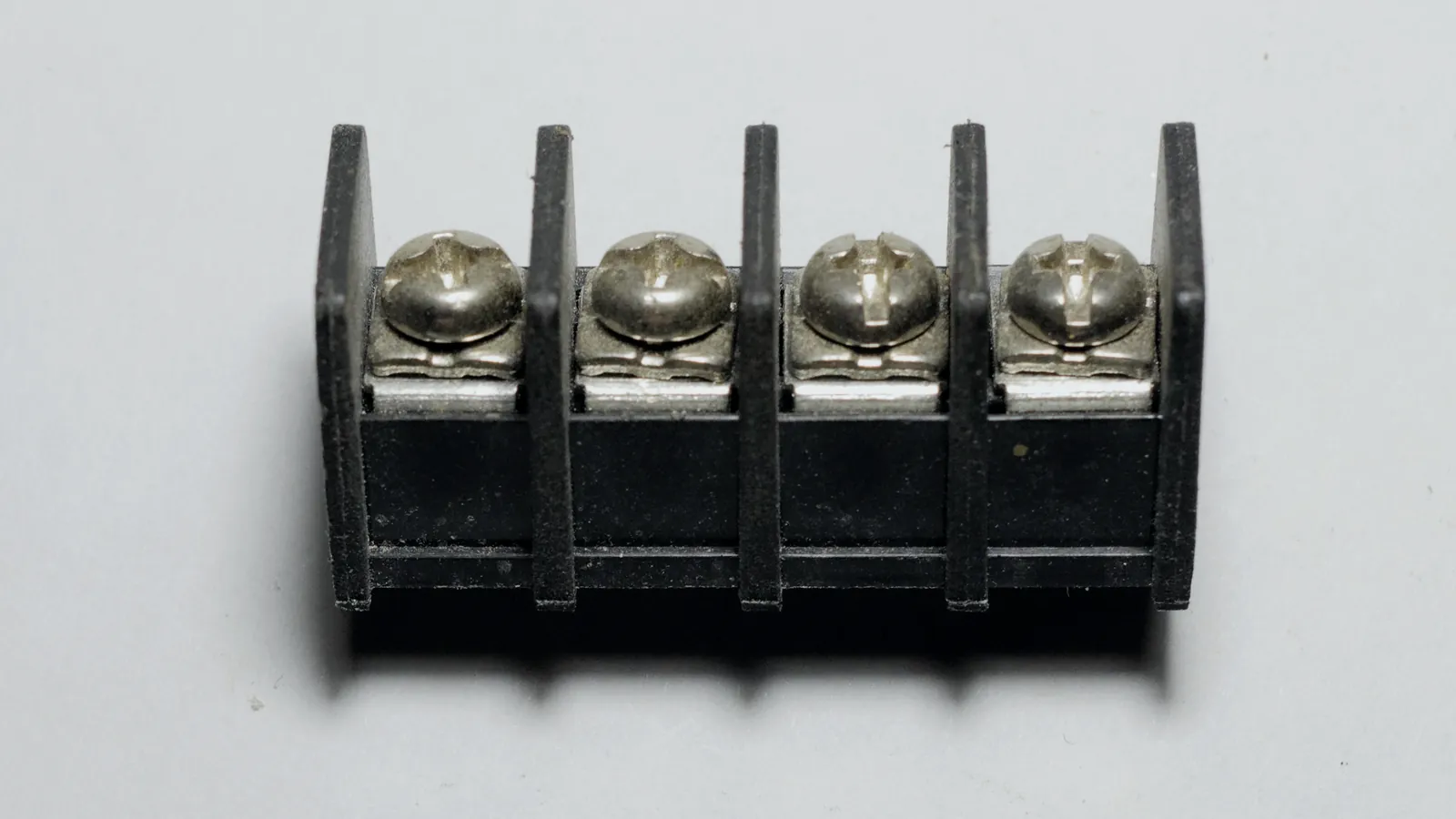
A 4-20 mA signal sends a measured value as current, with 4 mA for the lowest value and 20 mA for the highest; HART superimposes digital data on the same current so configuration and diagnostics can be read without extra wiring.
A transmitter is the instrument that turns a physical quantity, such as pressure, level or temperature, into that standard signal for a PLC, DCS, SCADA or indicator. Current is used instead of voltage because it stays the same along the whole loop. Cable resistance and small voltage drops do not change the reading, which matters on long runs across a tank farm.
The analogue direct-current signal range is standardised in IEC 60381-1. Most pressure, level, flow and temperature transmitters in Indonesian terminals and plants still deliver their main value this way, even when a digital bus runs beside them.
The loop
How a 4-20 mA loop works
A 4-20 mA loop is a simple series circuit: a power supply, the transmitter and the input of the control system share one current.
In the common two-wire, loop-powered design, the transmitter draws its own operating power from the loop and regulates the total current to match the measurement. Below its lowest output the electronics would starve, which is one reason the scale starts at 4 mA rather than 0 mA.
The PLC or DCS input measures the current, usually as the voltage across a precision resistor. Because every element is in series, an open wire anywhere drops the current to zero, and a short can push it above the normal range. Both cases are easy to tell apart from a real reading.
Four-wire transmitters, often analysers or flow meters, take power from a separate supply and drive the current output themselves. The input card must match: an active input supplies loop power, a passive input expects the transmitter or an external supply to do it. Mixing the two is a common commissioning mistake.
Good wiring keeps the loop quiet. Use a twisted, shielded pair, ground the shield at one end only, usually in the control room, and keep signal cables away from motor and VSD power cables. In hazardous areas the loop also passes an isolator or intrinsic safety barrier, and its voltage drop must fit within the supply budget, together with the transmitter and the input resistor.
Sets the loop current from 4 to 20 mA and adds the HART signal.
Hover, focus or tap a step to read its note.Scaling
Converting current to a process value
The current is a straight-line copy of the measurement: every 1.6 mA is one tenth of the range.
Each transmitter is configured with a lower range value (LRV) at 4 mA and an upper range value (URV) at 20 mA. The 16 mA between them span the whole range. The control system reverses the line: value = LRV + (I - 4) / 16 x (URV - LRV). The same formula works for any range, including ranges that start below zero such as vacuum or sub-zero temperature.
Most errors in scaling come from a range mismatch, not from the transmitter. If the transmitter is ranged 0 to 16 bar and the PLC is scaled 0 to 10 bar, every value is wrong by the same ratio. Check the range in both places, and check the unit, whenever a transmitter is replaced.
Loop current across the measuring range
| Label | Value |
|---|---|
| 0% | 4 mA |
| 25% | 8 mA |
| 50% | 12 mA |
| 75% | 16 mA |
| 100% | 20 mA |
Pressure transmitter, range 0 to 10 bar (LRV = 0 bar, URV = 10 bar)

value = LRV + (I - 4) / 16 x (URV - LRV)

I = 12.0 mA  ->  0 + (12.0 - 4) / 16 x 10  =  5.0 bar
I =  7.2 mA  ->  0 + ( 7.2 - 4) / 16 x 10  =  2.0 bar
I = 20.0 mA  ->  10.0 bar (top of range)
I =  3.5 mA  ->  below 3.6 mA: failure signal (NAMUR NE 43), not a reading

Reverse check: 2.5 bar should give 4 + 2.5 / 10 x 16 = 8.0 mAFault signals
Why 4 mA, not 0 mA, and what 3.6 mA means
Starting at 4 mA gives a "live zero": a healthy transmitter at the bottom of its range still sends current, so a reading of 0 mA can only mean a fault.
NAMUR recommendation NE 43 standardises how transmitters report their own failures through the current. As summarised in vendor documentation such as the Vaisala PR-33 user guide, the range from 3.8 to 20.5 mA carries measurement information. A current of 3.6 mA or less, or 21 mA or more, signals a diagnostic failure.
The small bands between 3.6 and 3.8 mA and between 20.5 and 21 mA show a process that has left the configured range. Set the alarm limits in the PLC to match these levels, and decide for each loop whether the transmitter should fail low or fail high. A level transmitter that fails high on a tank can trip a high-high alarm; one that fails low can hide an overfill.
- 0 mA
- Open loop or no power
- 3.6 mA or less
- Transmitter failure, low (NE 43)
- 3.8 to 4 mA
- Below range, still a measurement
- 4 to 20 mA
- Configured measuring range
- 20 to 20.5 mA
- Above range, still a measurement
- 21 mA or more
- Transmitter failure, high (NE 43)
HART
What HART adds to the loop
HART lets you talk to a transmitter digitally over the same two wires that carry its 4-20 mA signal.
The Siemens application guide "Working with HART networks" (AG012712, 2020) describes the method. The main process value stays on the analogue current. Everything else travels as Bell 202 frequency shift keying superimposed on it: a burst at 1200 Hz is a binary 1 and a burst at 2200 Hz is a binary 0. The bursts average to zero, so the slow 4-20 mA signal is generally not affected.
Through HART you can read the digital process value, secondary variables such as sensor temperature, the tag name, range settings and device diagnostics. HART is a master/slave protocol with up to two masters, typically the control system and a handheld communicator. The guide notes that HART was first developed in the early 1980s and that HART 7 devices use addresses 0 to 63.
| Criterion | 4-20 mA only | 4-20 mA with HART |
|---|---|---|
| Process value | One analogue value | Analogue value plus digital copy |
| Extra variables | None | Secondary values such as sensor temperature |
| Configuration | At the device, by local buttons or display | Remotely from the communicator or the asset system |
| Diagnostics | Failure current only (NE 43) | Detailed device status and alerts |
| Wiring | Two wires | Same two wires; at least 250 ohm loop resistance |
Calibration
Calibrating and checking a transmitter with HART
Calibration with HART means checking two things separately: that the sensor reads the true process value, and that the current output matches that reading.
A HART communicator connects in parallel across the loop, at the transmitter terminals or at the marshalling cabinet. It needs enough loop resistance to see the signal; the Siemens guide sets a minimum of 250 ohm, which most HART input cards already provide. With a laptop modem on a short bench loop, add the resistor yourself.
The analogue output can then be forced to fixed currents, for example 4, 12 and 20 mA, while someone reads the value on the HMI. This loop test proves the whole path from transmitter to screen without moving the process. Record every as-found and as-left value in the calibration sheet. Those records serve as evidence in audits and as the starting point when the same loop misbehaves again.
Isolate and inform
Put the loop in bypass or manual and tell the control room before touching it.
Connect and identify
Connect the communicator, confirm the tag, range and unit match the loop drawing.
Check the sensor
Apply known reference values with a calibrator and compare the digital reading.
Check the output
Run a loop test at fixed currents and compare with a reference meter and the HMI.
Trim only if needed
Trim sensor or output when the error exceeds the allowed tolerance, then recheck.
Record and restore
Save as-found and as-left values, remove the bypass and confirm with operations.
Protocols
HART vs Modbus: different jobs
HART and Modbus solve different problems: HART adds digital data to an analogue loop, while Modbus is a digital network on its own cable.
HART keeps the 4-20 mA value as the primary measurement and adds configuration and diagnostics on top. Its digital channel is slow; the Siemens guide puts the rate at about two messages per second. That is fine for setup and health checks, not for fast control. Multidrop HART exists, but the analogue value is then lost and the update rate drops further.
Modbus RTU puts many devices on one RS-485 pair and reads each by address, with no analogue signal at all. Tank gauges, flow computers and power meters often use it because they deliver many values per device. On a terminal you will find both: transmitters on 4-20 mA with HART into PLC inputs, and multi-value devices on Modbus into gateways.
| Criterion | HART | Modbus RTU |
|---|---|---|
| Medium | Superimposed on a 4-20 mA loop | Own RS-485 pair |
| Main value | Analogue current | Digital registers |
| Devices per cable | Usually one (point to point) | Many, by address |
| Typical use | Configuring and diagnosing transmitters | Reading gauges, meters and drives |
In the field
In the field: transmitter work at Citia sites
On Citia projects, most 4-20 mA problems are found during loop checks, before the plant relies on the signal.
At ITJ LPG Priok, areas PMB III and IV, Citia installed pressure and temperature transmitters whose data the PLC processes and the HMI displays. The work covered installation, calibration, wiring, configuration, testing and commissioning. Wiring and device communication problems were solved by checking the wiring thoroughly and adjusting the PLC and transmitter configuration.
During the Cikampek tank-monitoring upgrade, loop checks, I/O tests and functional tests verified every analogue and digital signal, alarm and interlock. The Field Instrumentation service delivers the same records as standard: datasheets, I/O lists, loop diagrams, calibration certificates and loop-check sheets.
Terms to know
- Transmitter
- An instrument that converts a physical quantity such as pressure or level into a standard signal for a control system.
- Current loop
- The series circuit of power supply, transmitter and input in which one current carries the measurement.
- LRV and URV
- Lower and upper range values: the process values that correspond to 4 mA and 20 mA.
- Live zero
- The practice of starting the scale at 4 mA so that 0 mA always indicates a fault.
- Loop-powered (two-wire)
- A transmitter that takes its operating power from the same two wires that carry the signal.
- HART
- Highway Addressable Remote Transducer: digital FSK communication superimposed on a 4-20 mA loop.
- HART communicator
- A handheld or laptop tool used to configure, test and diagnose HART devices.
- NAMUR NE 43
- A NAMUR recommendation that sets current levels for measurement and for transmitter failure signals.
- Loop test
- Forcing a transmitter output to fixed currents to check the path to the control system.
Frequently asked questions
Why does a transmitter signal start at 4 mA instead of 0 mA?
The signal starts at 4 mA so that a broken wire, which gives 0 mA, can never be mistaken for a real zero reading. The 4 mA also leaves enough current to power a two-wire transmitter at the bottom of its range.
What does a current below 3.8 mA mean?
A current below 3.8 mA means the signal has left the NAMUR NE 43 measuring band. Between 3.6 and 3.8 mA the process is below range; at 3.6 mA or less the transmitter is reporting a failure, and near 0 mA the loop is open or unpowered.
What is the difference between HART and Modbus?
HART adds digital data on top of a 4-20 mA loop, while Modbus is a separate digital network on RS-485 or Ethernet. HART is mainly for configuring and diagnosing one transmitter; Modbus reads many values from many devices on one cable.
How do I calibrate a transmitter with a HART communicator?
Calibrate a transmitter with HART by checking the sensor against a reference, then checking the current output with a loop test. Connect across at least 250 ohm, put the loop in bypass, record as-found values, trim only when out of tolerance, and record as-left values.
Does HART disturb the 4-20 mA reading?
HART generally does not disturb the 4-20 mA reading because its 1200 Hz and 2200 Hz bursts average to zero. Most analogue input cards filter the signal out. The Siemens guide notes that rare incompatibilities exist, so check the card when a reading jitters only during HART traffic.
What does a transmitter do?
A transmitter converts a measured physical quantity, such as pressure, level, flow or temperature, into a standard signal like 4-20 mA. The PLC, DCS or indicator reads that signal and turns it back into an engineering value.
Sources and further reading
- IEC 60381-1:1982 Analogue signals for process control systems, Part 1: Direct current signals (opens in a new tab)
- NAMUR Recommendations and Worksheets (NE 043, signal level for failure information of digital transmitters) (opens in a new tab)
- Default mA output value, PR-33 / PR-33-AC user guide (NAMUR NE 43 signal ranges) (opens in a new tab)
- SITRANS: Working with HART networks, application guide AG012712 (opens in a new tab)
- Pertamina ITJ LPG Priok: transmitter replacement in areas PMB III and IV (opens in a new tab)
- Field Instrumentation (opens in a new tab)
- Cover photo by Retired electrician, CC0 (opens in a new tab)
Next step
Prepare the technical discussion for your facility.
Bring the equipment list, diagrams and symptoms you have. The Citia team helps map the next step.
Related products and solutions
- KnowledgeWhat is a PLC? How it works, types and where it is usedA PLC reads inputs, runs logic in a repeating scan and drives outputs. How the scan works, what is in a PLC panel, the languages and the main types.
- KnowledgePipeline pressure monitoring and leak detection for fuel pipelinesPipeline pressure monitoring reads transmitters at several points and flags drops that do not fit the operating pattern; locating a leak needs extra methods such as line balance.
- KnowledgeWhat is Modbus? RTU vs TCP, registers and function codesModbus is an open protocol for industrial devices. This guide compares Modbus RTU and TCP and explains registers, function codes, frames and gateways.
- ProductField InstrumentationSelects, installs, calibrates and commissions the instruments that measure your process.
- ProjectPertamina ITJ LPG Priok: transmitter replacement in areas PMB III and IVPressure and temperature transmitters installed and integrated with the PLC and HMI in areas PMB III and IV of the Pertamina ITJ LPG Priok terminal.
- ProjectCikampek tank-monitoring upgradeTMS, integration and field testing
- ProductCATALYST PressMonLive pipeline pressure from field transmitters to the control room, with history and alarms.
- ProjectPressmon prototype for BalonganThe PressMon prototype is a miniature of the Pressure Monitoring System concept for the Balongan-Plumpang pipeline.
- ProjectPertamina Bitung integrated terminal: pump VSD and SCADA restorationRestoration of the field VSD pump system at the Bitung integrated terminal: new VSD units and pressure transmitter, fiber optic cable and AVEVA InTouch SCADA.