
Metering
Meter proving and flow computers: keeping fuel metering accurate
Meter proving tests a flowmeter against a known volume to give a meter factor; a flow computer applies it. Prover types, calculation and proving intervals.
- Topic
- Metering
- Updated
- 13 November 2026
- Reading time
- 3 min
- Sections
- 6
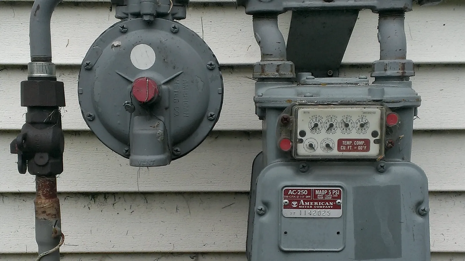
Meter proving is the test of a flowmeter against a known reference volume to produce a meter factor, while a flow computer applies that meter factor, together with temperature and pressure corrections, to calculate the standard volume of fuel delivered.
A meter that was accurate on the day of commissioning does not stay that way. Proving is how a terminal finds out how far it has moved, and the flow computer is where the answer is put to work. This guide is a technical follow-up to flowmeters for fuel. It covers the proving chain, how a meter factor is calculated, the types of prover, what a flow computer does and when to prove.
Process
The proving chain, from prover to report
Passes a known, calibrated volume past the meter.
Hover, focus or tap a step to read its note.Proving is a comparison, repeated until the runs agree.
The meter and the prover see the same flow of fuel. Several consecutive runs are taken at a steady flow rate, and the result is accepted only when the runs repeat within the limit set by the applicable procedure, such as API MPMS Chapter 4.8 on the operation of proving systems. Temperature and pressure at the prover and at the meter are recorded, because both volumes must be brought to the same conditions before they are compared.
Calculation
How a meter factor is calculated
A meter factor is the reference volume divided by the volume the meter indicated, both corrected to the same conditions.
A factor of exactly one means the meter agrees with the reference. A factor above one means the meter reads low, so its readings are multiplied up; below one means it reads high. The example on the right uses round, made-up numbers to show the arithmetic.
Do not confuse the meter factor with the K-factor. The K-factor is the number of pulses the meter emits per unit of volume, set by the meter's design. The meter factor is the small correction found by proving, applied on top of it.
Prover volume at base conditions : 1 000.00 L
Meter volume at the same conditions :   998.00 L

Meter factor = 1 000.00 / 998.00 = 1.0020

Later batch, meter indicates 5 000.0 L
Corrected volume = 5 000.0 x 1.0020 = 5 010.0 LComparison
Prover types compared
| Criterion | Test measure | Pipe prover | Small volume prover | Master meter |
|---|---|---|---|---|
| How it works | Fuel fills a calibrated vessel; the level is read at the neck | A sphere or piston travels between detectors over a calibrated length | A piston in a short calibrated volume; pulse interpolation adds resolution | A reference meter, itself proved, runs in series with the meter under test |
| Good for | Small meters, loading bays, aviation fuel | High flows, pipelines, marine transfer | Sites that want a compact fixed unit | Many meters, no room for a fixed prover |
| Limits | Manual, slower, volume per run is small | Large footprint and cost | Needs good detector and electronics care | Adds its own uncertainty to the chain |
Flow computer
What a flow computer calculates
A flow computer turns the meter's signal into a quantity that both parties can sign.
It is a dedicated device, not a general PLC, so its calculations are fixed, auditable and sealed. The calculation method follows API MPMS Chapter 12.2 on petroleum quantities from dynamic measurement, with temperature and pressure factors from the API tables. OIML R 117-1 adds that a correction device is an integral part of the meter, and that the uncorrected quantity shall not be shown in normal operation. It also forbids adjusting a meter by means of a bypass.
Count the pulses
Convert pulses to indicated volume with the K-factor.
Apply the meter factor
Multiply by the factor found at the last proving, for that product and flow rate.
Correct for temperature
Apply the temperature correction to bring volume to base conditions.
Correct for pressure
Apply the pressure correction where the product and pressure make it matter.
Report the quantity
Send gross and standard volume to the batch record, ticket and terminal system.
Practice
When to prove a meter
There is no single proving interval; the contract, the regulator and the meter's history set it.
Operators usually prove after a meter is installed, repaired or opened, after a change of product, when the flow range changes, and on a routine schedule. They then plot the meter factor over time.
A slow trend suggests wear or fouling. A step change points to a mechanical event, a different product or a set-up error. A factor that jumps between provings deserves a look at the prover and the temperature probes before the meter is blamed. Proving is the technical routine; tera ulang is the legal one, and both belong in the maintenance plan.
Field
Field notes: a flow computer in aviation fuel metering
At Pertamina Pulau Layang, the Citia aviation fuel metering integration uses an ISOIL VEGA II as the flow computer. It acquires and processes metering data from the field instruments. CS-Flow runs the dispatch logic, and the Machine User Interface identifies the user, takes the transaction by barcode and shows the filling in real time.
The page lists flow rate, gross volume, net volume, preset, loaded volume, temperature and status among the values operators monitor, and says the integration improves traceability and reduces manual recording errors. Details are in the Pulau Layang project. For how the batch controller relates, see what a batch controller does.
Glossary
- Meter factor
- Reference volume divided by the meter's indicated volume at the same conditions.
- K-factor
- Pulses emitted per unit of volume, set by the meter design.
- Prover
- Equipment that supplies a known volume to test a meter.
- Master meter
- A reference meter, itself proved, used to prove other meters.
- Pulse interpolation
- A technique that resolves fractions of a pulse so a short prover volume can give a precise result.
- Base conditions
- The reference temperature and pressure to which volumes are converted.
- Flow computer
- A dedicated device that calculates delivered quantity from the meter signal.
Frequently asked questions
What is a meter prover?
A meter prover is equipment that passes a known, calibrated volume through or past a flowmeter so the meter can be tested. Common types are the test measure, the pipe prover, the small volume prover and the master meter, which differ in size, speed and cost.
What is a meter factor?
A meter factor is the reference volume divided by the volume the meter indicated, both at the same conditions. A factor of one means the meter agrees with the reference, and the flow computer multiplies later readings by the factor to correct them.
How often should a flowmeter be proved?
There is no single interval; it is set by the contract, the regulator and the meter's history. Operators usually prove after repairs, product changes and flow range changes, plus on a routine schedule, then trend the meter factor to see drift.
What is the difference between a flow computer and a batch controller?
A flow computer calculates the delivered quantity, while a batch controller runs the loading: it opens and closes the valve and stops at the preset. At some bays one device does both, and at others they are separate and exchange data.
Does a flow computer replace proving?
No, a flow computer only applies the meter factor that proving produces. Without proving, the factor goes stale and the computer keeps calculating from an old number, so both are needed.
Sources and further reading
- API MPMS Chapter 4.8: Operation of Proving Systems (opens in a new tab)
- API MPMS Chapter 12.2: Calculation of Petroleum Quantities Using Dynamic Measurement Methods (opens in a new tab)
- OIML R 117-1 (2019): Dynamic measuring systems for liquids other than water, Part 1 (opens in a new tab)
- OIML R 117-2 (2019): Metrological controls and performance tests (opens in a new tab)
- Pertamina Pulau Layang: aviation fuel metering integration (opens in a new tab)
- Cover photo by HomeSpot HQ, CC BY 2.0 (cropped and colour graded) (opens in a new tab)
Next step
Prepare the technical discussion for your facility.
Bring the equipment list, diagrams and symptoms you have. The Citia team helps map the next step.
Related products and solutions
- KnowledgeVolume correction factor (VCF) and ASTM Table 54B explainedA volume correction factor (VCF) converts fuel volume at the measured temperature into volume at 15 °C. For refined products it comes from Table 54B.
- ProjectPertamina Pulau Layang: aviation fuel metering integrationIntegration of the ISOIL VEGA II flow computer, CS-Flow and the MUI at Pertamina Pulau Layang for safe, accurate and documented aviation fuel (avtur) dispatch.
- ProductCATALYST CT-BCConnects loading-bay batch controllers to the terminal system.
- KnowledgeFlowmeters for fuel: types, working principles and how to chooseFuel flowmeters measure volume or mass; PD, turbine and Coriolis are the usual choices at a loading bay. Compare principles, accuracy classes and selection.
- KnowledgeLegal metrology in Indonesia: verification (tera), re-verification and calibrationTera marks an instrument as valid for use, tera ulang repeats it periodically, and calibration gives no legal status. The rules and the process in Indonesia.
- KnowledgeBatch controllers in truck loading: function, operation and TAS integrationA batch controller loads a preset volume at the bay, stages the valve and stops on time. See how it works, how it links to a TAS and why batches overrun.